The following diagram is that of a pneumatic moment-balance differential pressure transmitter, similar to the Foxboro model 13A. The term “moment” refers to the physics principle of a force acting on a lever to produce a torque.
“Moment-balance” is more appropriate than “force-balance” in this case because the device pits moment against moment, rather than force against force directly:
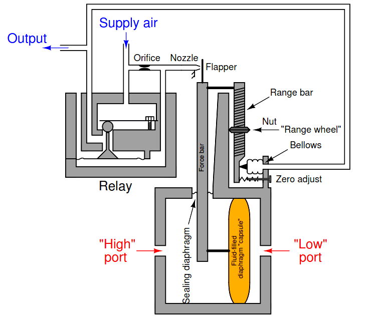
Describe this instrument’s response to an increasing differential pressure (increasing pressure on the “High” side, and steady pressure on the “Low” side; or decreasing pressure on the “Low” side with steady pressure on the “High” side), step by step.
Answer:
As the differential pressure increases (“high” side pressure increases relative to “low” side pressure):
End result: output pressure equals some proportion (multiple or fraction) of differential pressure across the diaphragm capsule.
1. Describe the purpose of the sealing diaphragm shown roughly mid-way along the length of the force bar.
2. Identify how this instrument will respond to obstructions (blockages) in the following locations:
→ Orifice
→ Nozzle
→ Vent (located on relay body)
Interest to add any further points? Share your answers with us through the below comments section.
Credits: Tony R. Kuphaldt
Learn an example PLC program to control a pump based on level sensors using ladder…
In the PLC timer application for security camera recording, when motion is detected then camera…
In this example, we will learn batch mixing with PLC ladder logic program using timer…
This PLC example on manufacturing line assembly is an intermediate-level PLC program prepared for the…
In this article, you will learn the PLC programming example with pushbutton and motor control…
This article teaches how to convert Boolean logic to PLC programming ladder logic with the…
