Inst ToolsInst ToolsInst Tools
  • Ask
  • Courses
  • Videos
  • Q & A
    • Interview
      • Instrumentation
      • Electronics
      • Electrical
      • Practical Questions
    • MCQ
      • Instrumentation MCQ
      • Electrical MCQ
      • Electronics MCQ
      • Control Systems MCQ
      • Analog Electronics MCQ
      • Digital Electronics MCQ
      • Power Electronics MCQ
      • Microprocessor MCQ
      • Multiple Choice Questions
  • EE
    • Electronics
      • Electronics Q & A
      • Electronic Basics
      • Electronic Devices & Circuits
      • Electronics Animation
      • Digital Electronics
    • Electrical
      • Electrical Basics
      • Electrical Q & A
      • Power Electronics
      • Electrical Machines
      • Electrical Animation
      • Power Systems
      • Switchgear & Protection
      • Transmission & Distribution
  • Measure
    • Control Valves
    • Calibration
    • Temperature
    • Pressure
    • Flow
    • Level
    • Analyzers
    • Switches
    • Vibration
    • Solenoid Valve
  • Control
    • PLC Tutorials
    • Control Systems
    • Safety Instrumented System (SIS)
    • Communication
    • Fire & Gas System
  • More
    • Design
    • Tools
    • Animation
    • Basics
    • Formulas
    • Standards
    • TextBooks
    • Common
    • Software
    • Excel Tools
    • Erection & Commissioning
    • Process Fundamentals
    • Videos
    • Books
Search
All rights reserved. Reproduction in whole or in part without written permission is prohibited.
Reading: PLC Programming for Train Detection and Gate Operation
Share
Notification Show More
Font ResizerAa
Inst ToolsInst Tools
Font ResizerAa
  • Courses
  • PLC Tutorials
  • Control Systems
Search
  • Ask
  • Courses
  • Videos
  • Q & A
    • Interview
    • MCQ
  • EE
    • Electronics
    • Electrical
  • Measure
    • Control Valves
    • Calibration
    • Temperature
    • Pressure
    • Flow
    • Level
    • Analyzers
    • Switches
    • Vibration
    • Solenoid Valve
  • Control
    • PLC Tutorials
    • Control Systems
    • Safety Instrumented System (SIS)
    • Communication
    • Fire & Gas System
  • More
    • Design
    • Tools
    • Animation
    • Basics
    • Formulas
    • Standards
    • TextBooks
    • Common
    • Software
    • Excel Tools
    • Erection & Commissioning
    • Process Fundamentals
    • Videos
    • Books
Follow US
All rights reserved. Reproduction in whole or in part without written permission is prohibited.
Inst Tools > Blog > PLC Tutorials > PLC Programming for Train Detection and Gate Operation

PLC Programming for Train Detection and Gate Operation

Learn the PLC programming for train detection and gate operation with warning alarms to open or close the railway gate.

Last updated: October 21, 2024 9:15 pm
Editorial Staff
PLC Tutorials
No Comments
Share
7 Min Read
SHARE

This article discusses an example of a PLC program to automatically control the railway crossing system with train detection and gate operation. This system is used to control the process of Opening and Closing railway crossing gates when a train passes. This system uses sensors to detect the arrival and departure of trains. When the system detects a train is coming, the system will automatically Close the crossing gates and Activate a warning Alarm. The system will re-Open the crossing gates after the train has passed the crossing, and the Alarm will be turned Off.

Contents
Train Detection and Gate OperationWhen a Train ComesWhen a train has passedProgram AddressingProgramming

Train Detection and Gate Operation

The PLC program uses 2 buttons and 4 sensors, the START_SYSTEM (I0.0) button is used to turn ON the system, and the STOP_SYSTEM (I0.1) button is used to turn OFF the system.

The SENS_TRAIN_COME (I0.2) sensor is used to detect an oncoming train, the SENS_TRAIN_LEFT (I0.3) sensor is used to detect a train that has passed a railway crossing, SENS_GATE_DOWN (I0.5) is used to limit the Gate position when Closing, and SENS_GATE_UP (I0.4) is used to limit the Gate position when Opening.

When a Train Comes

The SENS_TRAIN_COME (I0.2) sensor will be Active when it detects an oncoming train. The crossing gate will move CLOSED and the Output OUT_GATE_DOWN (Q0.1) will be ON. Alarm OUT_ALARM (Q0.2) becomes ON to provide a warning.

The crossing gate will Stop Closing when the SENS_GATE_DOWN (I0.5) sensor is Active, so the OUT_GATE_DOWN (Q0.1) Output will become OFF.

When a train has passed

The SENS_TRAIN_LEFT (I0.3) sensor will be Active when it detects that a train has passed a train crossing. 4 seconds later the crossing gate will OPEN. Output OUT_GATE_UP (Q0.0) becomes ON and Alarm OUT_ALARM (Q0.2) becomes OFF.

The OUT_GATE_UP (Q0.0) output will be OFF when the SENS_GATE_UP (I0.4) sensor is Active so that the crossing gate Stops Opening.
PLC Based Automatic Railway Gate Controller
Railway Gate Crossing Control Using PLC Automation

Program Addressing

CommentInput (I)Output (Q)Memory BitsTimer
START_SYSTEMI0.0   
STOP_SYSTEMI0.1   
SENS_TRAIN_COMEI0.2   
SENS_GATE_DOWNI0.5   
SENS_TRAIN_LEFTI0.3   
SENS_GATE_UPI0.4   
OUT_GATE_DOWN Q0.1  
OUT_GATE_UP Q0.0  
OUT_ALARM Q0.2  
SYSTEM_ON  M0 
IR_GATE_DOWN  M2 
IR_GATE_UP  M1 
IR_ALARM  M3 
IR_TIMER  M4 
TIMER_GATE   TM0

Programming

RUNG 0 (SYSTEM ON)

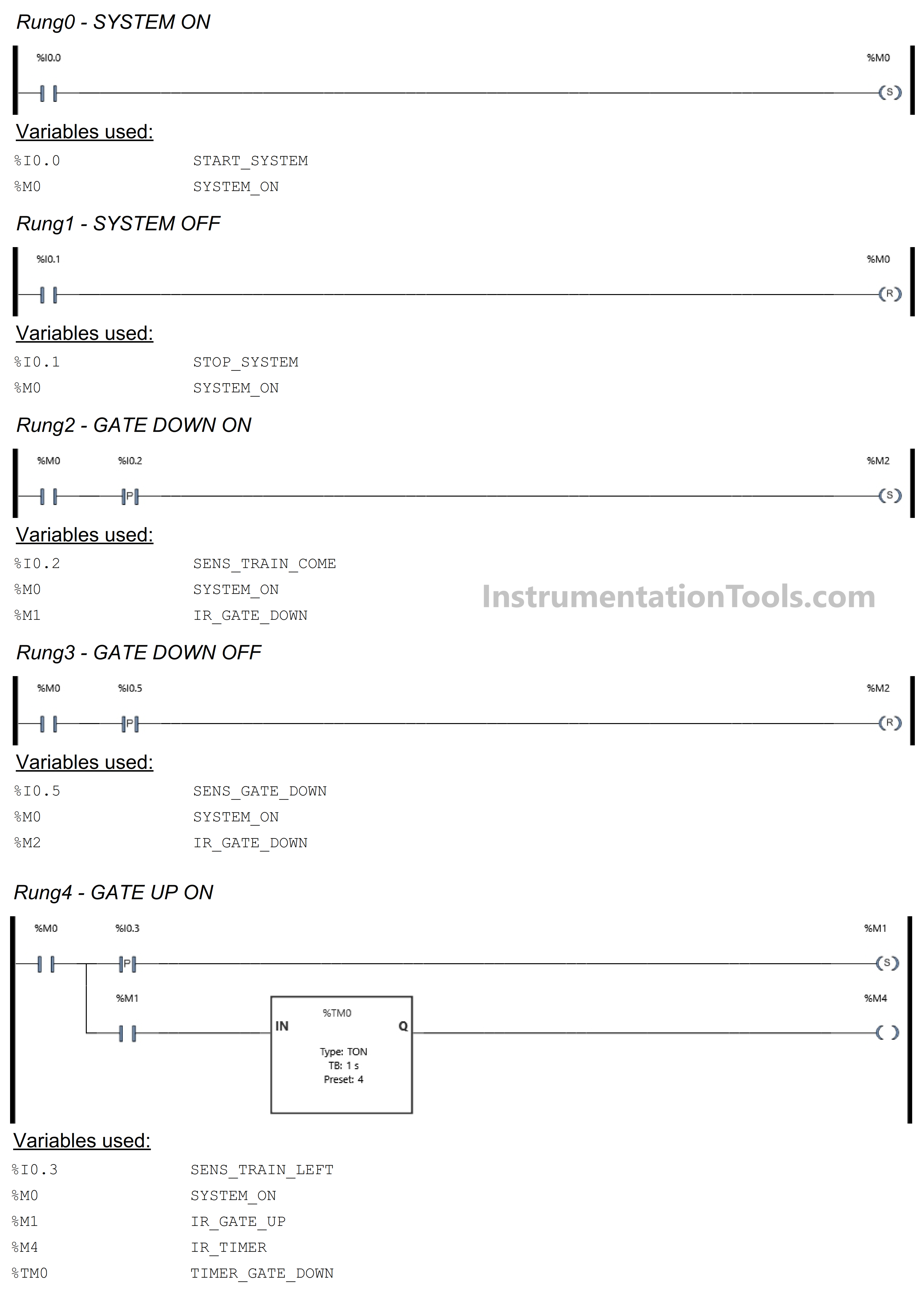
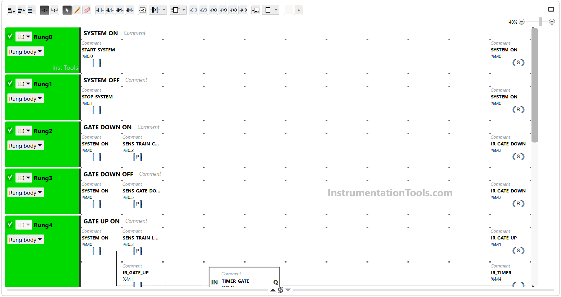
In this Rung, when the START_SYSTEM (I0.0) button is Pressed, the memory bit SYSTEM_ON (M0) will be in the HIGH state. The memory bit SYSTEM_ON (M0) remains in the HIGH state even though the START_SYSTEM (I0.0) button has been Released, because it uses the SET Coil Instruction.
PLC Programming for Train Detection and Gate Operation

RUNG 1 (SYSTEM OFF)

In this Rung, if the STOP_SYSTEM (I0.1) button is Pressed, the memory bit SYSTEM_ON (M0) will become LOW state. Because it uses the RESET Coil Instruction.

RUNG 2 (GATE DOWN ON)

In this Rung, when the NO contact of memory bit SYSTEM_ON (M0) and the SENS_TRAIN_COME (I0.2) sensor in the HIGH state, then the memory bit IR_GATE_DOWN (M2) will be in the HIGH state.

Because it uses the SET Coil Instruction, the memory bit IR_GATE_DOWN (M2) will remain in the HIGH state even though the SENS_TRAIN_COME (I0.2) sensor in the LOW state.

RUNG 3 (GATE DOWN OFF)

In this Rung, when the NO contact of memory bit SYSTEM_ON (M0) and the SENS_GATE_DOWN (I0.5) sensor in the HIGH state, the memory bit IR_GATE_DOWN (M2) will be in the LOW state. Because it uses the RESET Coil Instruction.
How to implement PLC programming for railway gate control

RUNG 4 (GATE UP ON)

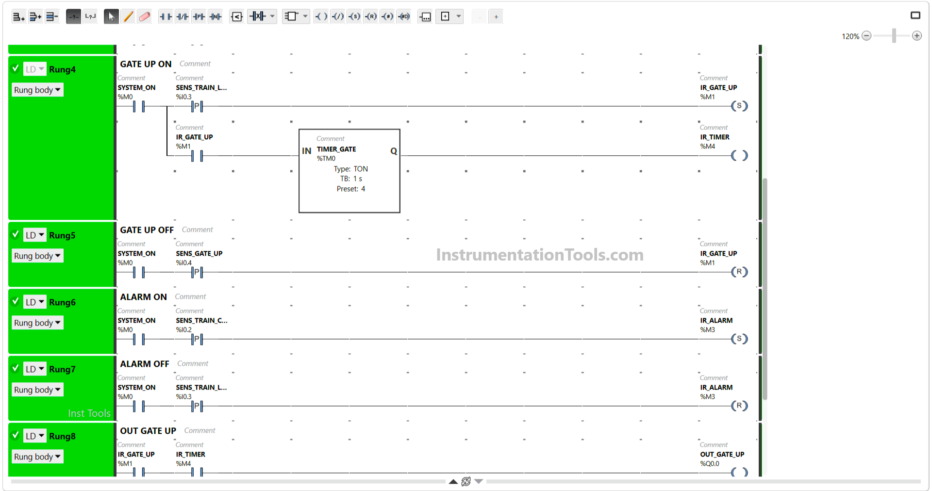
In this Rung, when the NO contact of memory bit SYSTEM_ON (M0) and the SENS_TRAIN_LEFT (I0.3) sensor in the HIGH state, then the memory bit IR_GATE_UP (M1) will become in the HIGH state and the TIMER_GATE (TM0) timer Starts counting up to 4 second.

Because it uses the SET Coil Instruction, the memory bit IR_GATE_UP (M1) will remain in the HIGH state even though the SENS_TRAIN_LEFT (I0.3) sensor in the LOW state.

After TIMER_GATE (TM0) has finished counting, the output memory bit IR_TIMER (M4) will be in the HIGH state.

RUNG 5 (GATE UP OFF)

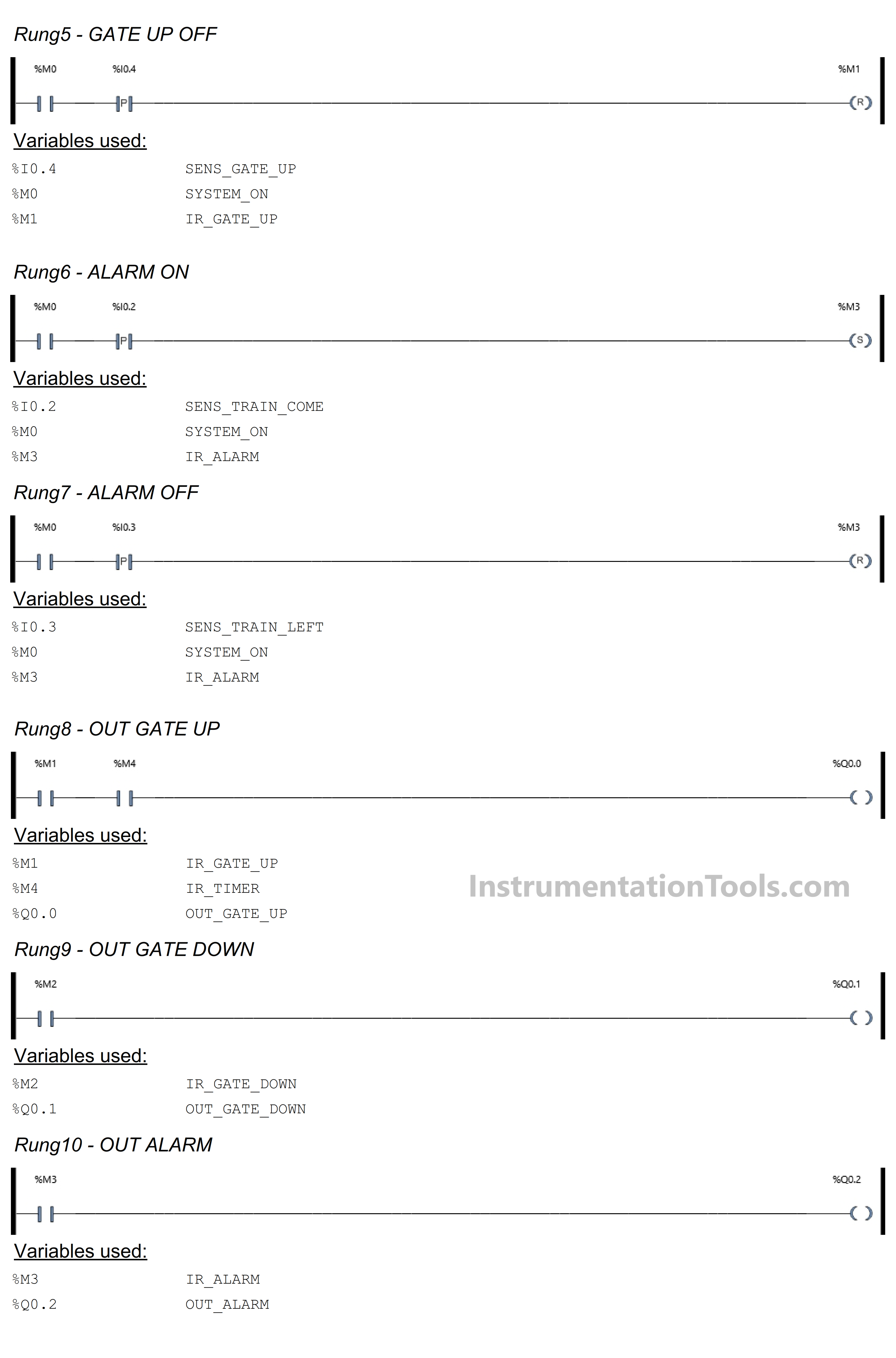
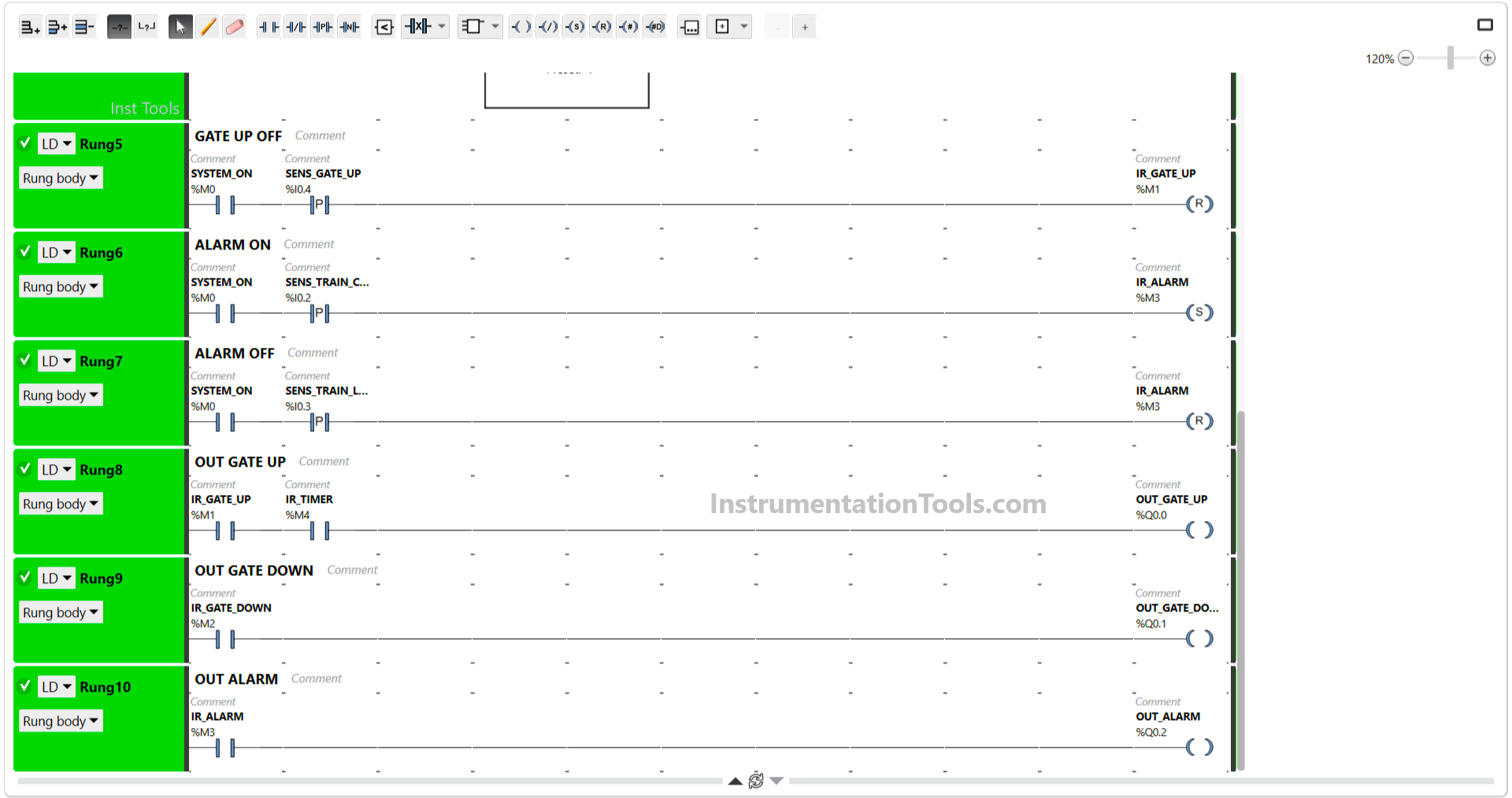
In this Rung, if the NO contact of memory bit SYSTEM_ON (M0) and the SENS_GATE_UP (I0.4) sensor in the HIGH state, then the memory bit IR_GATE_UP (M1) will be in the LOW state. Because it uses the RESET Coil Instruction.

RUNG 6 (ALARM ON)

In this Rung, the memory bit IR_ALARM (M3) will be in the HIGH state when the NO contacts of memory bit SYSTEM_ON (M0) and the SENS_TRAIN_COME (I0.2) sensor are in the HIGH state.

Because it uses a SET Coil, the memory bit IR_ALARM (M3) remains in the HIGH state even though the SENS_TRAIN_COME (I0.2) sensor in the LOW state.

RUNG 7 (ALARM OFF)

When the NO contact of memory bit SYSTEM_ON (M0) and the SENS_TRAIN_LEFT (I0.3) sensor in the HIGH state, the memory bit IR_ALARM (M3) will be in the LOW state. Because it uses the RESET Coil Instruction.
Railway Train Control Systems

RUNG 8 (OUT GATE UP)

In this Rung, when the NO contacts of memory bit IR_GATE_UP (M1) and IR_TIMER (M4) are in the HIGH state, the Output OUT_GATE_UP (Q0.0) will be ON.

RUNG 9 (OUT GATE DOWN)

In this Rung, when the NO contact of memory bit IR_GATE_DOWN (M2) in the HIGH state, the Output OUT_GATE_DOWN (Q0.1) will be ON.

RUNG 10 (ALARM OUTPUT)

In this Rung, when the NO contact of memory bit IR_ALARM (M3) in the HIGH state, the Output OUT_ALARM (Q0.2) will be ON.

Read Next:

  • PLC Product Painting with Weighing System
  • Studio 5000 PLC Program for Digital Alarms
  • Vacuum Cleaner Programming in Omron PLC
  • Washing Machine Automation PLC Program
  • Functional Block Diagram Analog Alarm Logic
Don't Miss Our Updates
Be the first to get exclusive content straight to your email.
We promise not to spam you. You can unsubscribe at any time.
Invalid email address
You've successfully subscribed !
InTouch SCADA Login Password Security
How to Create Faceplate in FactoryTalk View Studio?
Design a Program Using Studio 5000 and FactoryTalk View Studio
Comparing ICS and IT Systems Security
Industrial Automation Engineers Interview Questions
Share This Article
Facebook Whatsapp Whatsapp LinkedIn Copy Link
Share
Leave a Comment

Leave a Reply Cancel reply

Your email address will not be published. Required fields are marked *

Stay Connected

128.3kFollowersLike
69.1kFollowersFollow
208kSubscribersSubscribe
38kFollowersFollow

Categories

Recent Comments

  • Guifty Shimica on Top Non-PLC Certification Courses for Automation Professionals
  • Guifty Shimica on Top Non-PLC Certification Courses for Automation Professionals
  • MIHARITSOA Aina Sitraka on Top Non-PLC Certification Courses for Automation Professionals
  • Vaishnavi on Free Instrumentation Course for Trainee Engineers

Related Articles

PLC Motor Logic with START, STOP, TEST Push buttons

PLC Motor Logic with START, STOP, TEST Push buttons

Creating Logic in Intouch Using Scripting

Create Logic with InTouch Scada using Scripting

Create Ladder Diagram from Boolean Logic

Create Ladder Diagram from Boolean Logic

Simatic S7 PLC Backup Steps

How to take Backup from Siemens S7-300 PLC?

Design Counters in PLC Programming With a Move Instruction

Design Counters in PLC Programming With a Move Instruction

PLC Program for Water filling and Discharging Process

PLC Program for Water filling and Discharging Process

Hardwired IO and Serial IO - Differences Explained

Hardwired I/O and Serial I/O – Differences Explained

VFD Interview Questions and Answers

VFD Interview Questions and Answers – Electrical Drives

More Articles

Types of Calibration

Types of Calibration

Direct Acting Actuators

Effect of Differential Pressure on Control Valve Lift

How to Delay a Sensor Signal in PLC?

How to Delay a Sensor Signal in PLC?

Paint Mixing System

Paint Mixing System

Power Systems Questions & Answers

Power Systems MCQ Series 3

HMI

Learn about SCADA and HMI Systems

Project Management of Safety Instrumented System

Project Management of Safety Instrumented System (SIS)

What is a Condensate Pot? How to Install it?

Follow US
All rights reserved. Reproduction in whole or in part without written permission is prohibited.
Welcome Back!

Sign in to your account

Username or Email Address
Password

Lost your password?