PLC Program to control paint spraying of objects.
Problem Description
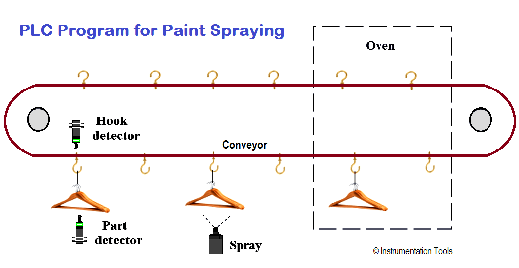
Design automatic spray painting of objects which are moving on the conveyor using PLC ladder diagram.
Also Read : PLC Program for Automatic Heating & Mixing of Products
For this application, we used S7-300 PLC and TIA portal software for programming.
When START PB (I0.0) pressed master coil (Q0.0) will be ON and it can be stopped by pressing STOP PB (I0.1).
When master coil is ON, oven (Q0.1) will start.
When part is detected, relay coil will be set for logic purpose. And it will set the first bit of MW10.
Here we used bit shift register so after detection of part it will count hanger detection and after. Here assume distance of spray from part detector proximity is 3 steps. So as per shift register logic M10.2 will be ON after 3 steps.
When M10.2 is ON, spray will be activated.
Note :- Above application may be different from actual application. This example is only for explanation purpose only. We can implement this logic in other PLC also. This is the simple concept of spray painting of parts in industries, we can use this concept in other examples also.
All parameters and graphical representations considered in this example are for explanation purpose only, parameters or representation may be different in actual applications. Also all interlocks are not considered in the application.
Also Read : PLC Program for Conveyor System
Author: Bhavesh
If you liked this article, then please subscribe to our YouTube Channel for PLC and SCADA video tutorials.
You can also follow us on Facebook and Twitter to receive daily updates.
Read Next:
The PLC panel and MCC panel interface signals are start, stop, run feedback, trip, local…
In this article, we are going to discuss about shutter door control using induction motor…
Electrical Drives control the motion of electric motors. Motion control is required in industrial and…
PLC ladder logic design to control 3 motors with toggle switch and explain the program…
VFD simulator download: Master the online tool from the Yaskawa V1000 & programming software for…
The conveyor sorting machine is widely used in the packing industries using the PLC program…


View Comments
formidable leçon merci de votre part