This is a PLC Program for controlling conveyors ON sequence and OFF sequence.
PLC Controls Conveyors ON and OFF Sequence
Problem Description
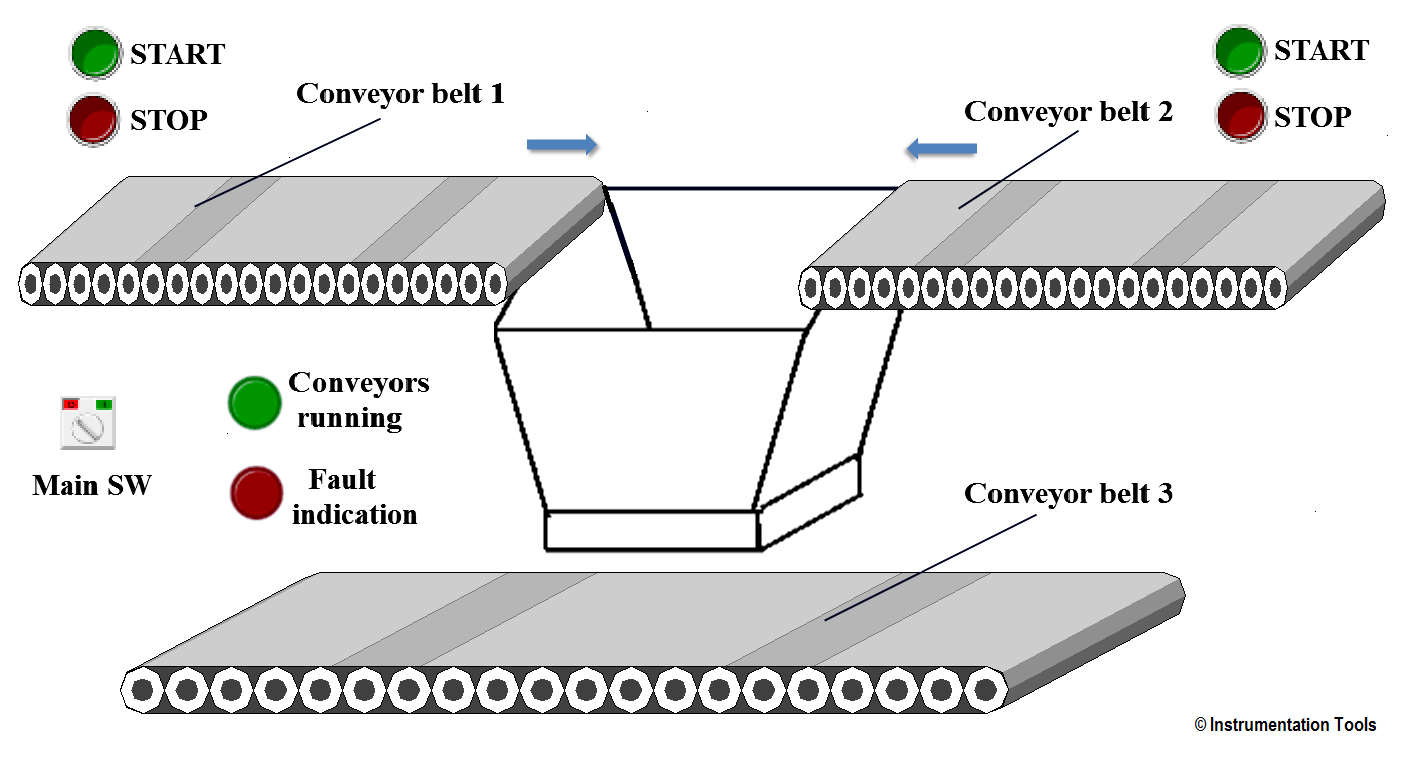
There are three belt conveyor in the system. We need to control sequences of conveyors both ON sequence and OFF sequence.
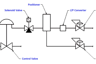
Problem Diagram
Problem Solution
We will use PLC S7-300 for this application. Also we will use TIA portal software for programming.
Conveyor belt 1 or conveyor belt 2 can be started by the corresponding START push buttons and can be stopped by corresponding STOP push buttons.
Conveyor belt 3 should always transport when either conveyor belt 1 or conveyor belt 2 is transporting.
When OFF push button is pressed, belt 1 or belt 2 is to continue running for 20 sec. and belt 3 for 60 seconds to clear the belts of material and Then stopped.
There is 10 Hz. monitoring signal for belt status monitoring for all three belts. If there is fault in any one of the belts then the entire belt should turn off immediately.
And OFF indications of previously running belts should flash with 5 HZ frequency.
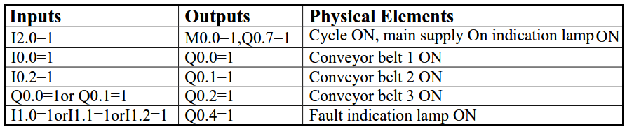
List of inputs & outputs
List of inputs
- System ON/OFF switch :- I2.0
- Belt 1 START :- I0.0
- Belt 1 STOP :- I0.1
- Belt 2 START :- I0.2
- Belt 2 STOP :- I0.3
- Belt 1 fault :- I1.0
- Belt 2 fault :- 1.1
- Belt 3 fault :- I1.2
List of outputs
- Conveyor belt 1 :- Q0.0
- Conveyor belt 2 :- Q0.1
- Conveyor belt 3 :- Q0.2
- Belts running indication :- Q0.3
- Fault indication :- Q0.4
- Fan 3 ON Indication :- Q0.6
- Main supply ON indication :- Q0.7
M memory
- Cycle ON :- M0.0
- 5HZ clock pulse :- M0.5
- 10HZ clock pulse :- M1.0
PLC control conveyors ON sequence and OFF sequence
Program Explained
For this application, we used S7-300 PLC and TIA portal software for programming.
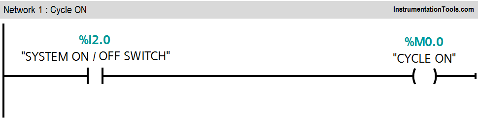
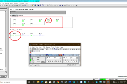
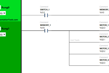
Network 1:
When system ON switch (I2.0) is pressed, cycle ON (M0.0) bit will be ON.
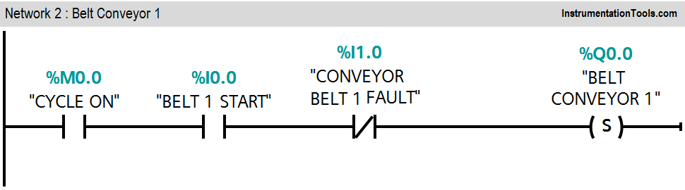
Network 2:
When belt 1 START PB (I0.0) is pressed, Conveyor belt 1(Q0.0) will be ON.
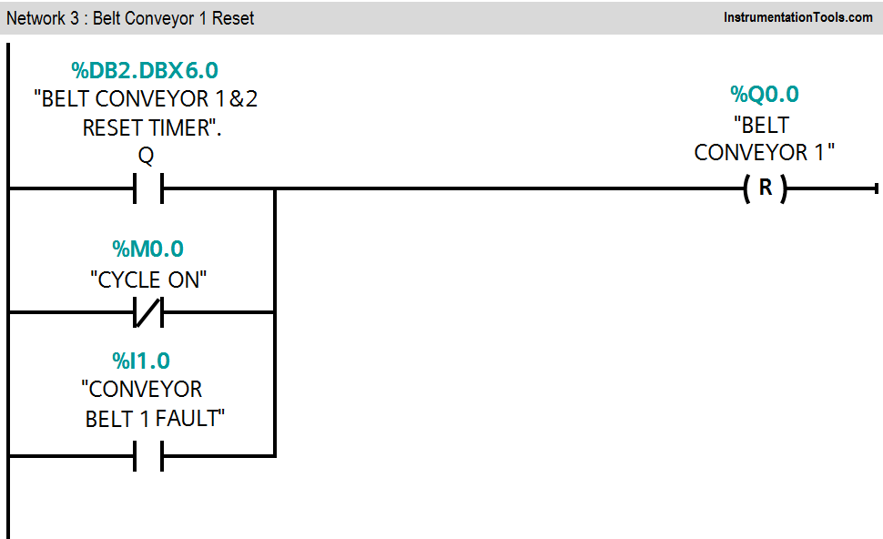
Network 3:
When conveyor belt 1 STOP button (I0.1) is pressed, timer will start to count time and after 20s timer will stop the conveyor belt 1 (Q0.0). If fault occur in conveyor belt 1, belt 1 should be STOP.
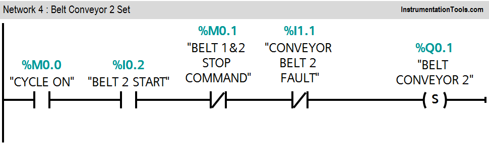
Network 4:
When belt 2 START PB (I0.2) is pressed, conveyor belt 2 (Q0.1) will be ON.
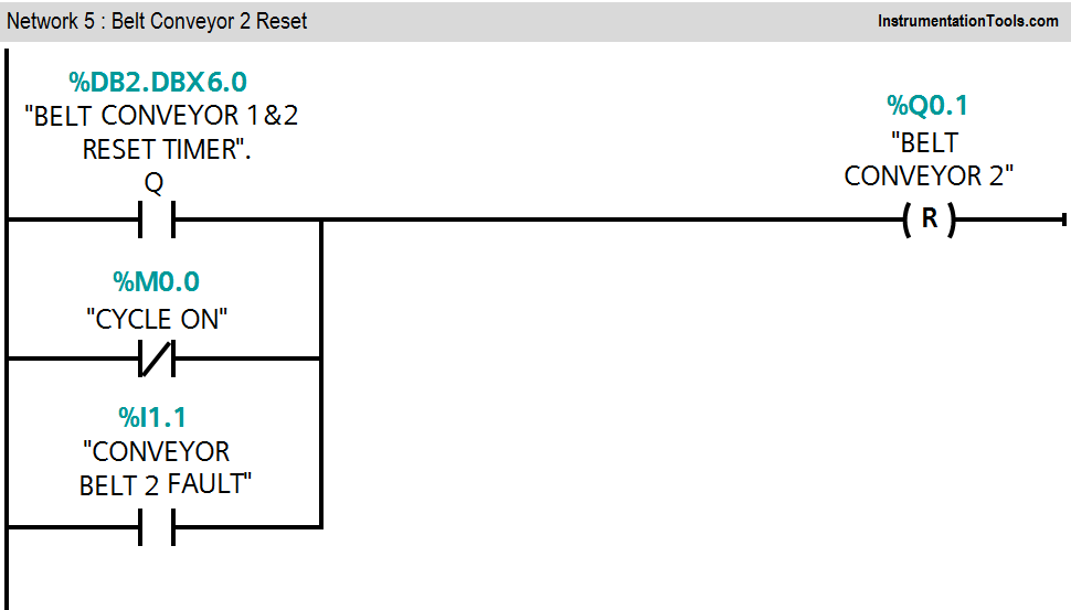
Network 5:
When conveyor belt 2 STOP button (I0.3) is pressed, Timer will start to count time and after 20s timer will stop the conveyor belt 2 (Q0.1). If fault occur in conveyor belt 2, belt 2 should be STOP.
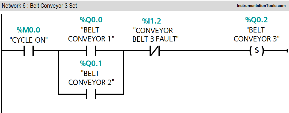
Network 6:
Either conveyor belt 1 (Q0.0) or conveyor belt 2 (Q0.1) is ON, Conveyor belt 3 (Q0.2) will be ON. If fault occur in conveyor belt 3, it should be STOP.
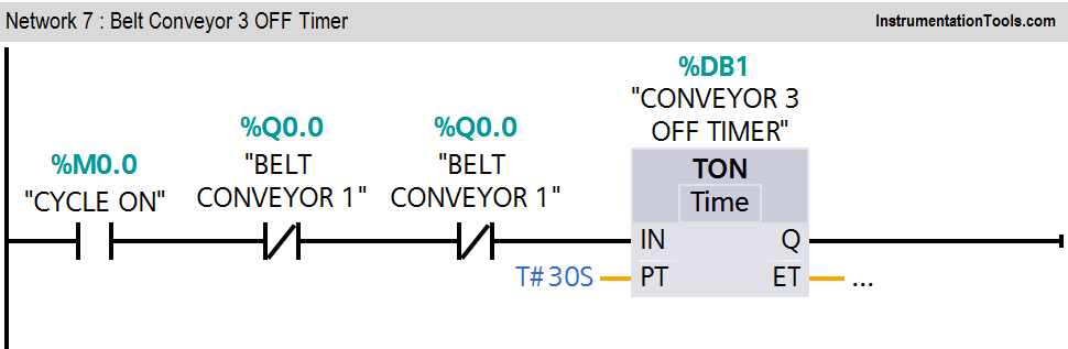
Network 7:
When both conveyors are OFF, Conveyor 3 off timer will be executed.
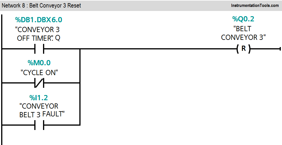
Network 8:
When conveyor belt 3 timer is executed, after 30s it will stop the conveyor belt 3 (Q0.2).
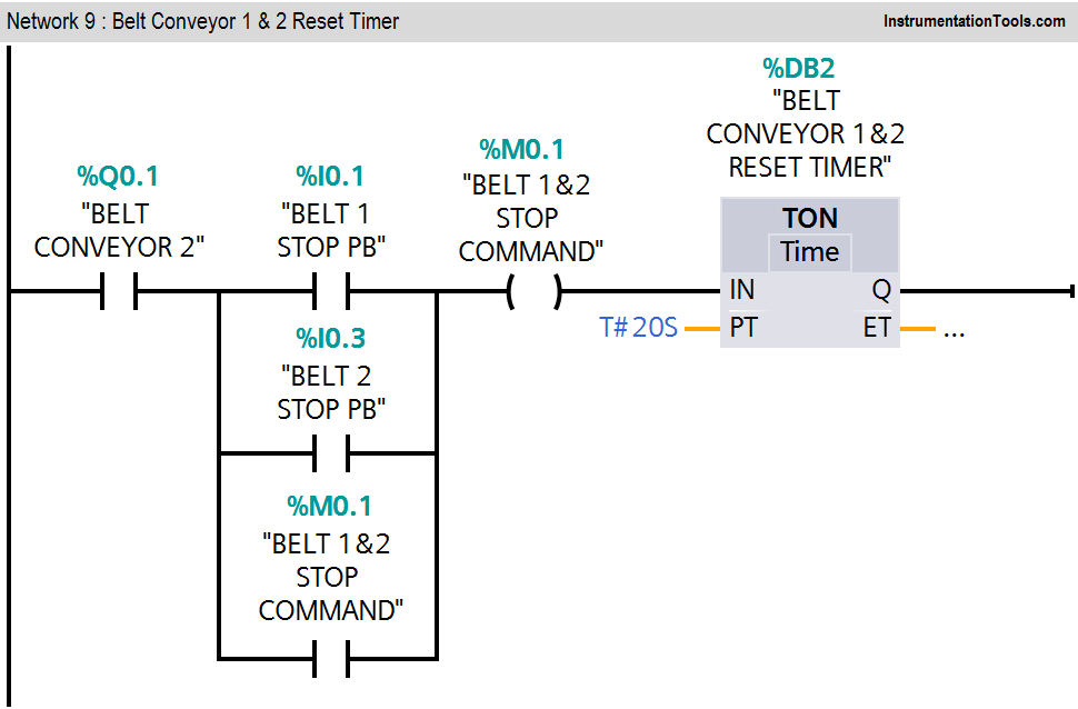
Network 9:
Either conveyor belt 1 STOP PB (I0.1) or conveyor belt 2 STOP PB (I0.3) is pressed, conveyor 1&2 reset timer will be executed.
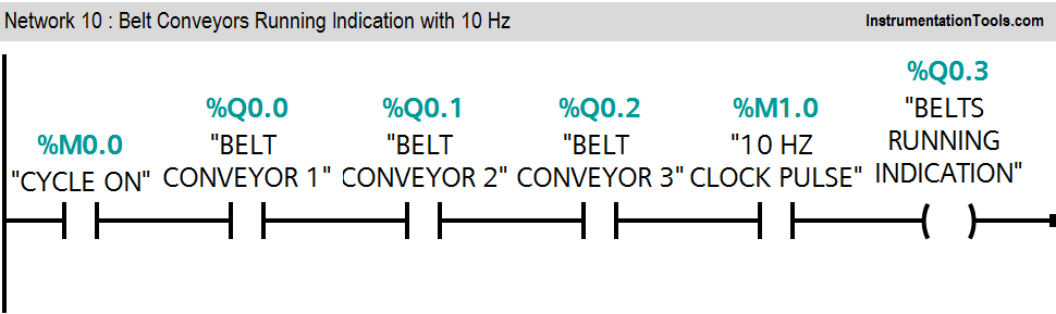
Network 10:
If three conveyors are running in healthy condition, belts running indication lamp (Q0.3) blinks on 10HZ frequency.
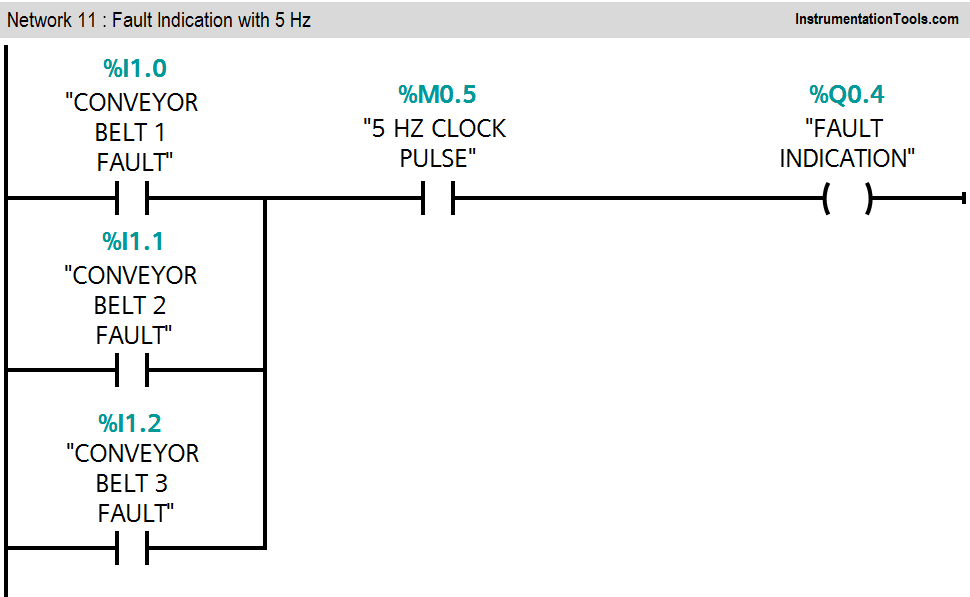
Network 11:
If any conveyor belt is faulty out of three belts, fault indication lamp (Q0.7) will start to blink on 5HZ frequency.
Note :- Above application may be different from actual application. This example is only for explanation purpose only. We can implement this logic in other PLC also. This is the simple concept of conveyor ON and conveyor OFF sequence in industry, we can use this concept in other examples also.
All parameters considered in example are for explanation purpose only, parameters may be different in actual applications. Also all interlocks are not considered in the application.
Result
Author: Bhavesh
If you liked this article, then please subscribe to our YouTube Channel for PLC and SCADA video tutorials.
You can also follow us on Facebook and Twitter to receive daily updates.
Read Next:
- Difference Between SCADA and HMI
- Coffee Vending Machine – PLC Logic
- PLC Training Software Download
- Split Range Control using PLC
- Raw Counts to Engineering Units


Sir, error in network 7 repeated output Q0.0 in XIO twice