Inst ToolsInst ToolsInst Tools
  • Courses
  • Videos
  • Q & A
    • Interview
      • Instrumentation
      • Electronics
      • Electrical
      • Practical Questions
    • MCQ
      • Instrumentation MCQ
      • Electrical MCQ
      • Electronics MCQ
      • Control Systems MCQ
      • Analog Electronics MCQ
      • Digital Electronics MCQ
      • Power Electronics MCQ
      • Microprocessor MCQ
      • Multiple Choice Questions
  • EE
    • Electronics
      • Electronics Q & A
      • Electronic Basics
      • Electronic Devices & Circuits
      • Electronics Animation
      • Digital Electronics
    • Electrical
      • Electrical Basics
      • Electrical Q & A
      • Power Electronics
      • Electrical Machines
      • Electrical Animation
      • Power Systems
      • Switchgear & Protection
      • Transmission & Distribution
  • Measure
    • Control Valves
    • Calibration
    • Temperature
    • Pressure
    • Flow
    • Level
    • Analyzers
    • Switches
    • Vibration
    • Solenoid Valve
  • Control
    • PLC Tutorials
    • Control Systems
    • Safety Instrumented System (SIS)
    • Communication
    • Fire & Gas System
  • More
    • Design
    • Tools
    • Animation
    • Basics
    • Formulas
    • Standards
    • TextBooks
    • Common
    • Software
    • Excel Tools
    • Erection & Commissioning
    • Process Fundamentals
    • Videos
    • Books
Search
All rights reserved. Reproduction in whole or in part without written permission is prohibited.
Reading: PLC Motor Logic with START, STOP, TEST Push buttons
Share
Notification Show More
Font ResizerAa
Inst ToolsInst Tools
Font ResizerAa
  • Courses
  • PLC Tutorials
  • Control Systems
Search
  • Courses
  • Videos
  • Q & A
    • Interview
    • MCQ
  • EE
    • Electronics
    • Electrical
  • Measure
    • Control Valves
    • Calibration
    • Temperature
    • Pressure
    • Flow
    • Level
    • Analyzers
    • Switches
    • Vibration
    • Solenoid Valve
  • Control
    • PLC Tutorials
    • Control Systems
    • Safety Instrumented System (SIS)
    • Communication
    • Fire & Gas System
  • More
    • Design
    • Tools
    • Animation
    • Basics
    • Formulas
    • Standards
    • TextBooks
    • Common
    • Software
    • Excel Tools
    • Erection & Commissioning
    • Process Fundamentals
    • Videos
    • Books
Follow US
All rights reserved. Reproduction in whole or in part without written permission is prohibited.
Inst Tools > Blog > PLC Tutorials > PLC Motor Logic with START, STOP, TEST Push buttons

PLC Motor Logic with START, STOP, TEST Push buttons

Last updated: March 4, 2021 3:21 pm
Editorial Staff
PLC Tutorials
2 Comments
Share
3 Min Read
SHARE

Design the ladder logic for controlling the running state of the single phase motor by pressing START and STOP pushbuttons i.e. motor should remain in ON state after START pushbutton is pressed and should OFF when STOP pushbutton is pressed. We also have to check if the motor is running normally by pressing TEST pushbutton?

  • I0.0 – START pushbutton to Start Motor
  • I0.1 – STOP pushbutton to Stop Motor
  • I0.2 – Error signal from Motor to PLC.
  • Q0.0 –Single phase Motor
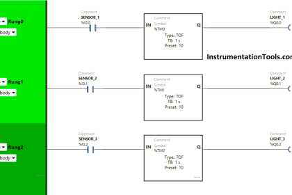
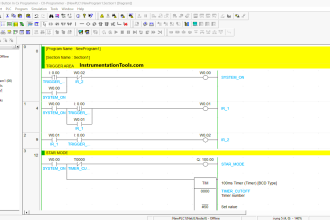
PLC Motor Logic

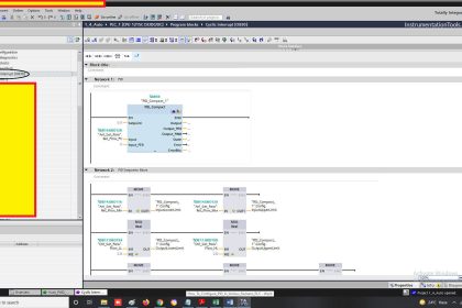
Press START button and I0.0 is ON. The Motor will keep running if no error occurred (I0.3 is OFF). The action can be practiced by a latching circuit which takes output Q0.0 as one of the input condition to keep the motor running even if the START button is not pressed (See normally open contact Q0.0 below I0.0).

Contents
Design the ladder logic for controlling the running state of the single phase motor by pressing START and STOP pushbuttons i.e. motor should remain in ON state after START pushbutton is pressed and should OFF when STOP pushbutton is pressed. We also have to check if the motor is running normally by pressing TEST pushbutton?PLC Motor LogicProblem :Case 2 : TEST Push button NC contact in series with LATCH
PLC Motor Logic with START, STOP, TEST Push buttons

When STOP button is pressed, I0.1 is ON and Q0.0 is OFF. The motor will stop running. If any error is occurred (I0.3 is ON), Y1 will be OFF and the motor will stop running.

When TEST is pressed (I0.2 is ON), Q0.0 is ON. The motor will start running if no error occurred (I0.3 is OFF). On the contrary, when TEST is released, the motor will stop running. The testing function is performed by this process.

Problem :

Here in the above logic, once motor started with TEST push button, we have to use STOP push button for stopping the motor. Because once motor started, the Latch  (Q 0.0) will activate and keep the motor running even after release of TEST push button

Case 2 : TEST Push button NC contact in series with LATCH

The above problem can be solved when we use NC contact of TEST push button in series with LATCH (Q 0.0) as shown in below figure. When we run the motor using TEST push button, the LATCH will not activate because the NC contact of TEST push button becomes NO.

 In real time applications, we may use Time Delays, One Shot Rise Pulse Inputs, Set – Reset and other instructions within the logic to avoid problems.

Motor Ladder Logic

NOTE : Sometimes we may consider STOP push button within the TEST logic of motor. This is an example of the plc motor logic.

If you liked this article, then please subscribe to our YouTube Channel for PLC and SCADA video tutorials.

You can also follow us on Facebook and Twitter to receive daily updates.

Read Next:

Motor Control Circuit

PLC Permissive for Motor

Up Counter PLC Program

Concept of Latching in PLC

PLC based Door Control

Don't Miss Our Updates
Be the first to get exclusive content straight to your email.
We promise not to spam you. You can unsubscribe at any time.
Invalid email address
You've successfully subscribed !

Recommended Articles

How is Data Stored in Standard Modbus Protocol?
Difference Between PLCSIM and PLCSIM Advanced? – Siemens PLC
Use of Comments in SCL Language
Electrical and Instrumentation – Automation Pre-engineering Documents
How to Communicate with Excel from Intouch SCADA?
Siemens S7-300 CPU Suffix Explanation
Share This Article
Facebook Whatsapp Whatsapp LinkedIn Copy Link
Share
2 Comments
  • Dino Difento says:
    July 20, 2019 at 12:54 pm

    i test motor logic above on my plc. when test button is released, the motor still running because a latching is running. this is caused by motor which link with latching

    Reply
  • S Bharadwaj Reddy says:
    July 20, 2019 at 3:11 pm

    Thank you for the comment. Please see updated article.

    Reply

Leave a Reply Cancel reply

Your email address will not be published. Required fields are marked *

Stay Connected

128.3kFollowersLike
69.1kFollowersFollow
208kSubscribersSubscribe
38kFollowersFollow

Categories

Recent Comments

  • William Snyder on Top Non-PLC Certification Courses for Automation Professionals
  • Kamli on Top Free PLC Software
  • Guifty Shimica on Top Non-PLC Certification Courses for Automation Professionals
  • Guifty Shimica on Top Non-PLC Certification Courses for Automation Professionals

Related Articles

Pump and Mixer Operations Example PLC Timer-Based Control

Pump and Mixer Operations Example: PLC Timer-Based Control

Factory IO PLC Course

Factory I/O PLC Automation Training Course (Free)

How PLC controls a ON-OFF Valve

PLC Valve Control Ladder Logic Programming

Cars Garage Counter From the Same Door PLC Logic

Cars Garage Counter From the Same Door PLC Logic

Compare Servo Motor and Stepper Motor

Compare Servo Motor and Stepper Motor

PLC Latched Circuit Example

PLC Latching Function

Omron PLC real-time clock street lighting program

Automatic Highway Lights Program using RTC in Omron PLC

PLC ON DELAY TIMER FUNCTION

#6 PLC Best Practices – Validate Timers and Counters

More Articles

Sink or source PNP or NPN Normally Open or Normally Closed Input v. output. output

Sink or Source? Normally Open or Normally Closed?

Measurement and Instrumentation Objective Questions

Measurements & Instrumentation Quiz – Set 1

Electrical Machines Questions and Answers

Electrical Machines Torque Production Quiz

Electrical Machines Questions and Answers

DC Machines Efficiency and Testing Quiz

Instrumentation During the Detail Design Phase

Instrumentation Engineer Activities & Documents – Detail Design Phase

IEC 60909 and IEC 61363 for Short Circuit

Difference Between IEC 60909 and IEC 61363 for Short Circuit

IR Radio Sensors Objective Questions

IR Radio Sensors Objective Questions

Thermodynamic cycle

Thermodynamic Cycles in Power Plant

Follow US
All rights reserved. Reproduction in whole or in part without written permission is prohibited.
Welcome Back!

Sign in to your account

Username or Email Address
Password

Lost your password?