Inst ToolsInst ToolsInst Tools
  • Courses
  • Automation
    • PLC
    • Control System
    • Safety System
    • Communication
    • Fire & Gas System
  • Instrumentation
    • Design
    • Pressure
    • Temperature
    • Flow
    • Level
    • Vibration
    • Analyzer
    • Control Valve
    • Switch
    • Calibration
    • Erection & Commissioning
  • Interview
    • Instrumentation
    • Electrical
    • Electronics
    • Practical
  • Q&A
    • Instrumentation
    • Control System
    • Electrical
    • Electronics
    • Analog Electronics
    • Digital Electronics
    • Power Electronics
    • Microprocessor
  • Request
Search
  • Books
  • Software
  • Projects
  • Process
  • Tools
  • Basics
  • Formula
  • Power Plant
  • Root Cause Analysis
  • Electrical Basics
  • Animation
  • Standards
  • 4-20 mA Course
  • Siemens PLC Course
Reading: PLC Logic Example on Multiple Switches and Motors
Share
Font ResizerAa
Inst ToolsInst Tools
Font ResizerAa
  • Courses
  • Design
  • PLC
  • Interview
  • Control System
Search
  • Courses
  • Automation
    • PLC
    • Control System
    • Safety System
    • Communication
    • Fire & Gas System
  • Instrumentation
    • Design
    • Pressure
    • Temperature
    • Flow
    • Level
    • Vibration
    • Analyzer
    • Control Valve
    • Switch
    • Calibration
    • Erection & Commissioning
  • Interview
    • Instrumentation
    • Electrical
    • Electronics
    • Practical
  • Q&A
    • Instrumentation
    • Control System
    • Electrical
    • Electronics
    • Analog Electronics
    • Digital Electronics
    • Power Electronics
    • Microprocessor
  • Request
Follow US
All rights reserved. Reproduction in whole or in part without written permission is prohibited.
Inst Tools > Blog > PLC Tutorials > PLC Logic Example on Multiple Switches and Motors

PLC Logic Example on Multiple Switches and Motors

Learn the PLC logic example on multiple switches and motors with the ladder diagram.

Last updated: March 20, 2024 7:38 am
Editorial Staff
PLC Tutorials
No Comments
Share
5 Min Read
SHARE

Learn the PLC logic example on multiple switches and motors with the ladder diagram.

Contents
PLC Logic ExamplePLC Logic VideoInputs of PLCOutputs of PLCMultiple Switches and Motors Ladder LogicProgram ExplainedPLC Simulation Results

This PLC logic example is prepared for the engineering students to learn and practice the ladder logic. The design of the same PLC program for industrial usage will be different.

PLC Logic Example

Problem Statement:

Design a PLC ladder logic for the following application.

There is a use of four toggle switches to control four motors.

If Switch 1 is ON, then Motor I will be ON.

If Switch 2 is ON, then Motor I and Motor II will be ON.

If Switch 3 is ON, then Motor I, Motor II, and Motor III will be ON.

If Switch 4 is ON, then Motor I, Motor II, Motor III, and Motor IV will be ON.

PLC Logic Video

We explained the above PLC example logic in the below video. Follow the step-by-step procedure prepared for the beginners.

Example of Multi-Switch to Multi-Motor Program in PLC Programming

Inputs of PLC

The list of the digital inputs for this PLC logic is mentioned below.

Switch 1: I0.0

Switch 2: I0.1

Switch 3: I0.2

Switch 4: I0.3

Outputs of PLC

The required digital outputs are listed below.

Motor 1: Q0.0

Motor 2: Q0.1

Motor 3: Q0.2

Motor 4: Q0.3

Multiple Switches and Motors Ladder Logic

Here is the PLC logic for the given problem statement.
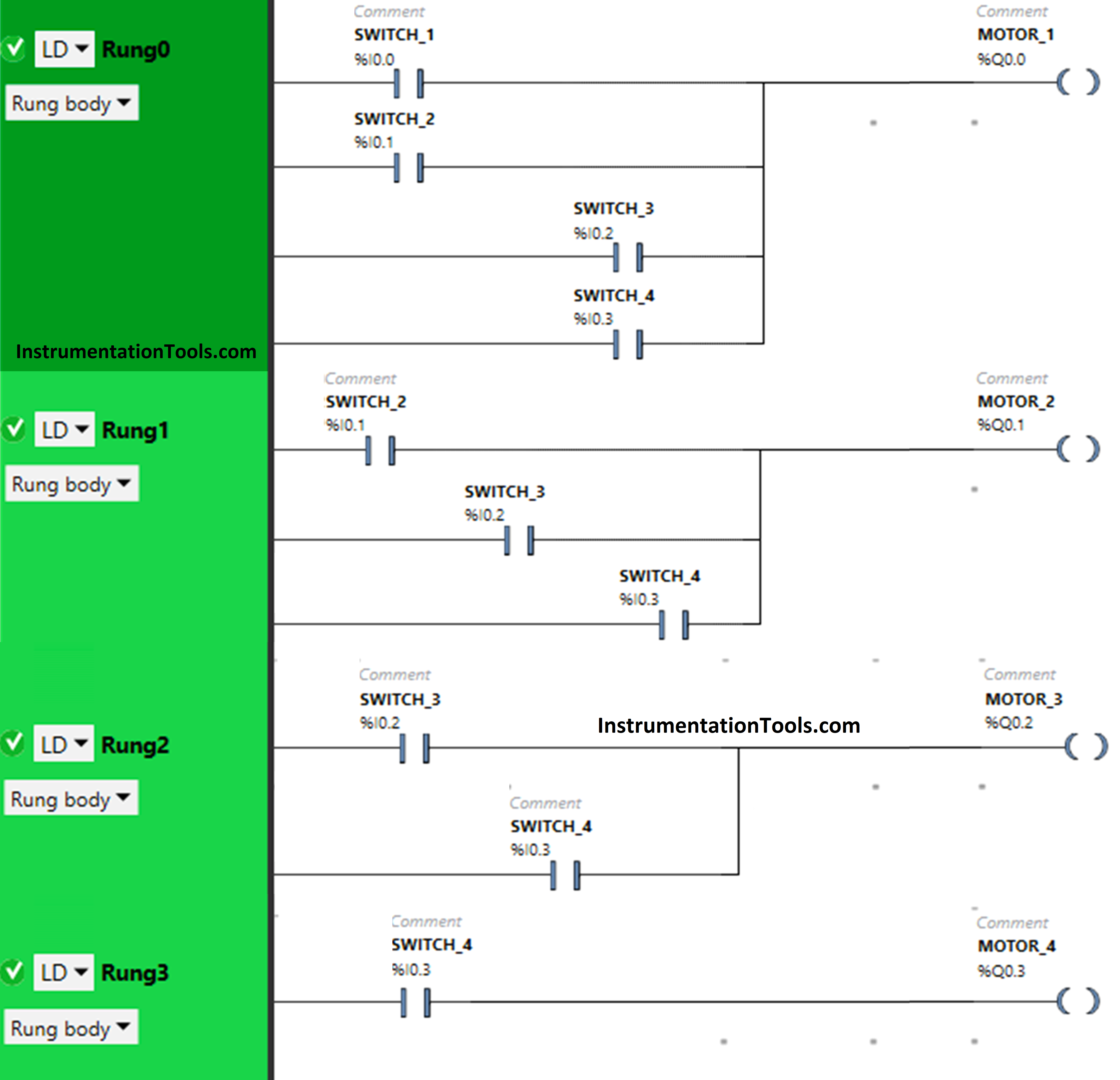
PLC Logic Example on Multiple Switches and Motors

Program Explained

For this example, we used Schneider PLC software for programming.

In the above PLC program, we have used Normal Open Contact for Switch 1 (I0.0), Switch 2 (I0.1), Switch 3 (I0.2) and Switch 4 (I0.3)

Switch 1, Switch 2, Switch 3, and Switch 4 are connected in parallel for Motor 1, thus implementing OR logic gate.

For Motor 2, inputs switch 2, switch 3, and switch 4 are connected in parallel, thus implementing OR logic gate.

Switch 3 and switch 4 are implementing OR logic gate i.e., connected in parallel for Motor 3.

Only Switch 4 is connected to Motor 4.

For Motor 1 to be ON, either Switch 1 or Switch 2 or Switch 3 or Switch 4 should be ON.

To turn ON Motor 2, either Switch 2 or Switch 3 or Switch 4 should be ON.

When Switch 3 or Switch 4 is ON, then Motor 3 will turn ON.

Motor 4 will turn ON when Switch 4 is turned ON.

PLC Simulation Results

Next, we will see the PLC simulation results with different input switch ON and OFF combinations.

When Switch 1 is ON
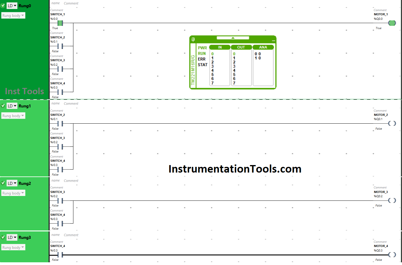
PLC Ladder Logic for Four Motors drive Simultaneously

When the toggle switch 1 is turned ON, the current flows through it (here we are using the term “Current” in case of an electrical circuit, so here you can assume it as “Current” or simply call it as “Signal”).

As a result, Motor 1 gets ON. Other motors will remain OFF because Switch 1 is not connected to them.

When Switch 2 is ON
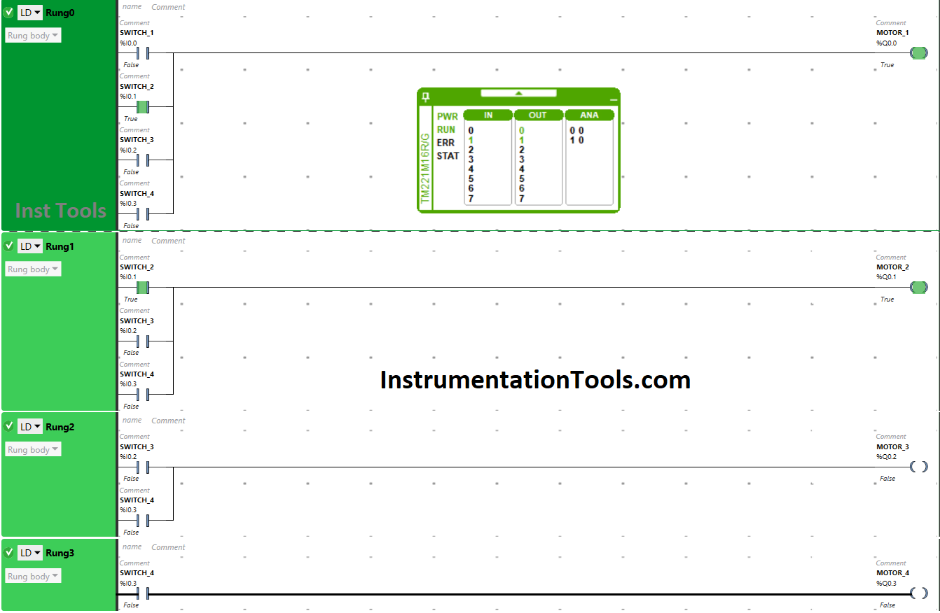
Multiple Switches and Motors Ladder Diagram

The current will flow through switch 2 when it is turned ON that will turn ON Motor 1 and Motor 2. It is so because switch 2 is connected to Motor 1 and Motor 2 only.

When Switch 3 is ON
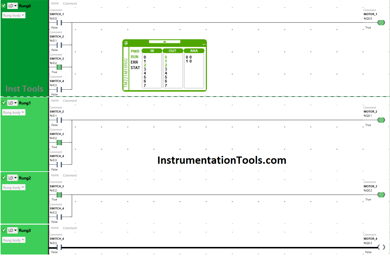
How can we make the ladder logic for a toggle switch

When Switch 3 is turned ON, the current flows through it that will turn ON three motors i.e., Motor 1, Motor 2 and Motor 3. The input switch 3 is connected to these outputs only. Motor 4 will remain OFF as Switch 3 is not connected to it.

When Switch 4 is ON
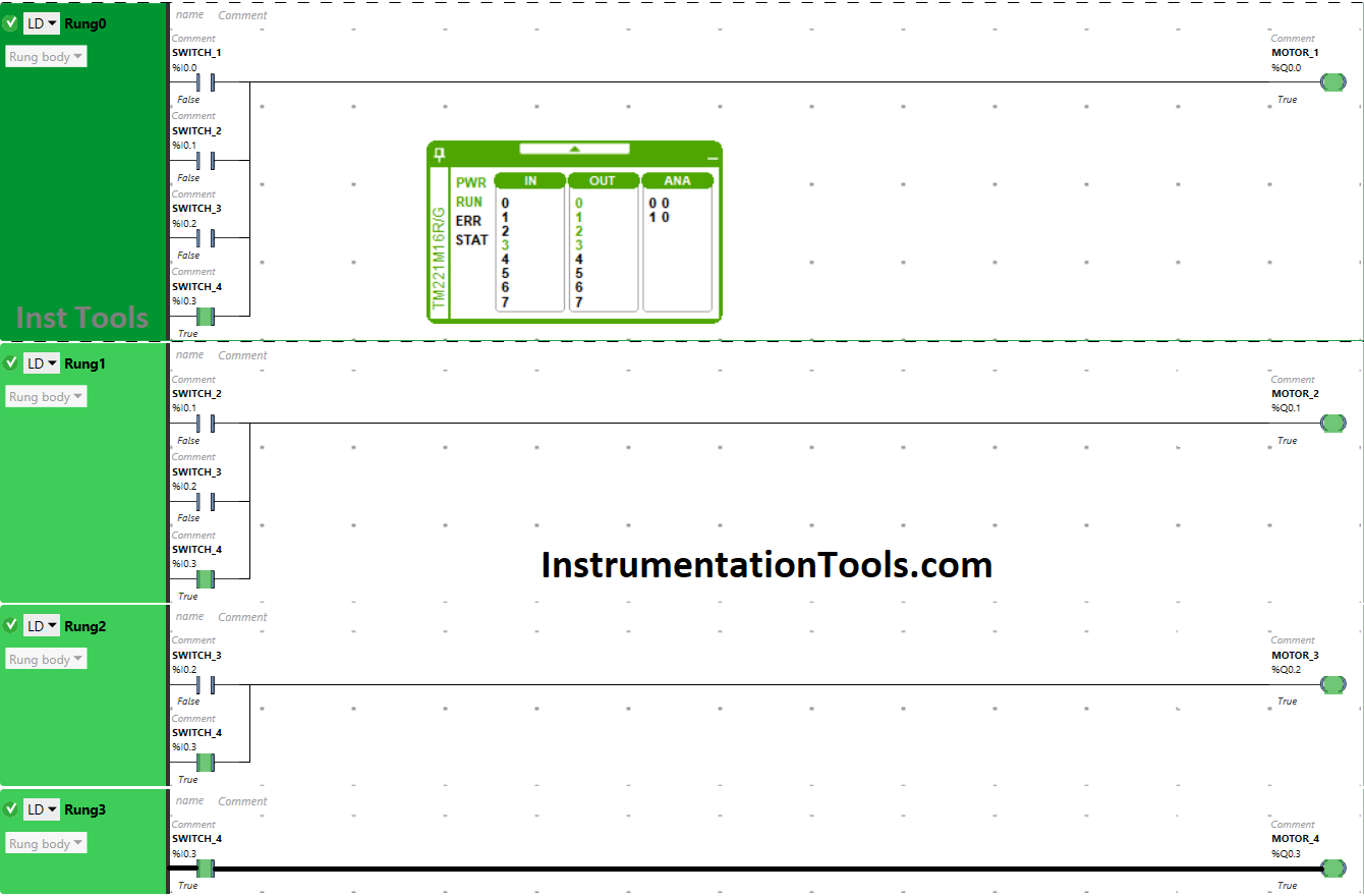
PLC Fundamentals and Examples

Switch 4 will turn ON all the motors when turned ON. Switch 4 is connected to all the motors, when turned ON, Motor 2, Motor 2, Motor 3 and Motor 4 will turn ON.

If you liked this article, then please subscribe to our YouTube Channel for PLC and SCADA video tutorials.

You can also follow us on Facebook and Twitter to receive daily updates.

Read Next:

  • Siemens Control System (TDC)
  • Electrical Diagram into PLC Program
  • How to Choose a PLC for a Project?
  • PLC Example to Control LEDs Via Switches
  • Siemens Communication using I-Device
Don't Miss Our Updates
Be the first to get exclusive content straight to your email.
We promise not to spam you. You can unsubscribe at any time.
Invalid email address
You've successfully subscribed !

Continue Reading

PLC Program for Automatic Parameter Initialization When Power UP
Configuration of Input and Output Tags in Siemens Scada and PLC
Data Types in PLC – Bit, Byte, Integer, Real, String
What is Thin Client in SCADA? – Purpose, Advantages
Conveyor Speed Logic using Structured Text in PLC
Exhaust Fan Control: Example of PLC Timer Programming
Share This Article
Facebook Whatsapp Whatsapp LinkedIn Copy Link
Share
Leave a Comment

Leave a Reply Cancel reply

Your email address will not be published. Required fields are marked *

Stay Connected

128.3kFollowersLike
69.1kFollowersFollow
210kSubscribersSubscribe
38kFollowersFollow

Categories

Explore More

PLC Valve Control Ladder Logic Programming
80+ PLC MCQ Questions
Parts of PLC
How to Program PID Control in PLC with Structured Text?
PLC Memory Mapping and I/O addressing
Free Allen Bradley PLC Ladder Logic Training Course
How to Troubleshoot Siemens PLC Programs?
PLC based Auto/Manual Operation of Roll down Shutters in Industry

Keep Learning

Simatic Hardware Configuration

Configuration of Profibus Network in Siemens PLC

Conveyor and Puncher PLC Program

Toggle Switch & Sensor: Conveyor and Puncher PLC Program

PLC Ladder Logic Door Open and Closing System

Which Language is Best for PLC Programming?

Preventa XPS MC, XPS MP - Safety controllers

High-end Programmable Logic Controller – Schneider PLC

Burning Oven PLC Program

PLC Program for Ceramic Burning Oven Conveyor System

Machine Indicator Lights PLC Programming Solution

Machine Indicator Lights: PLC Programming Solution

PLC Data Logging and Transmission

Moving Data between PLCs – Siemens Basics – TSEND TRCV

PLC Automatic Control of Two Outputs with one Input

PLC Automatic Control of Two Outputs with one Input

Learn More

Automatic Motor Forward and Reverse Control using Timer

Automatic Motor Forward and Reverse Control using Timer

U-tube Water Manometer

How much Pressure applied to U-tube Water Manometer?

Motion Detection based Street Light PLC Logic Solution

Motion Detection based Street Light: PLC Logic Solution

Pulse Generation using Timer in Siemens PLC

Pulse Generation using Timer in Siemens PLC

Power Systems Questions & Answers

Power Systems MCQ Series 4

Top Non-PLC Certification Courses for Automation Professionals

Top Non-PLC Certification Courses for Automation Professionals

Mass Spectrometer Questions and Answers

Magnetic Deflection Mass Spectrometer Questions & Answers

Ph Meter Principle

pH measurement

Menu

  • About
  • Privacy Policy
  • Copyright

Quick Links

  • Learn PLC
  • Helping Hand
  • Part Time Job

YouTube Subscribe

Follow US
All rights reserved. Reproduction in whole or in part without written permission is prohibited.
Welcome Back!

Sign in to your account

Username or Email Address
Password

Lost your password?