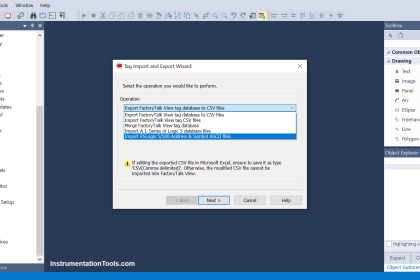
Instruction list language is a bit of old type language which is not preferred by many programmers due to it’s lengthy sequence of coding. But still, it is easy to learn and if you know all the mnemonics, then you can write the program easily. This post is intended to give the programmers an insight on how to write a program in instruction list language. Starting with this post, we will first see some basic instructions that we use normally in all of the programs. We will use the Schneider software of Machine Expert Basic for our purpose.
PLC Instruction List Program
Let us understand the case scenario first. When the start button is pressed, a lamp turns on and the cycle runs; condition to that stop button is not pressed and the cycle has not been completed. Once the lamp turns on, we check the sensor whether it is more than 300 or not. If it is more, then wait for 5 seconds, and turn on the motor.
When the motor rotates, a sensor is mounted on the assembly which counts the number of rotations. When it matches 10, then the cycle should stop as it has been completed. All the timers and counters along with the outputs should remain off if the cycle is in stop condition. If the motor is on and the sensor goes low in any instant, then the motor will turn off. But, the counts will not be reset.
Basic Instructions
We will write the logic now. We have the following PLC inputs – start button, stop button and counting sensor. We have the following PLC outputs – lamp and motor. We will use Machine Expert Basic software and write it in instruction list language.
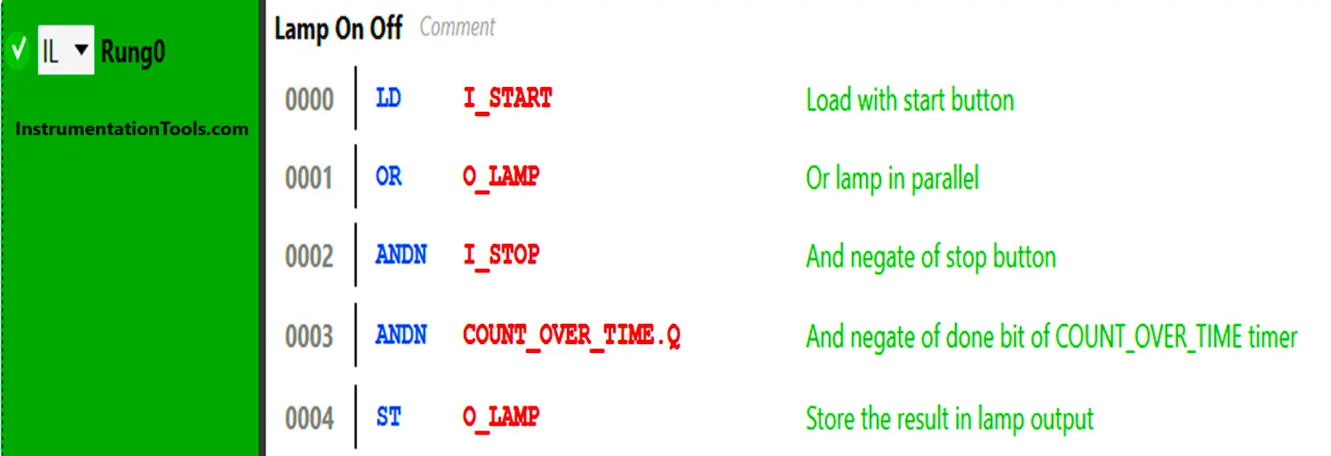
See the first rung written. As you can see, single instructions are written in a line and every code has it’s meaning. LD (load) is a normal NO element. OR is the OR instruction we use for parallel operation. ANDN is the AND instruction which works in a negate way. ST (store) is the normal coil operation. So, the sequence is like – if the start button is on or the lamp bit is on, and the stop button is off, and the count_over_time is not done, then the lamp turns on.
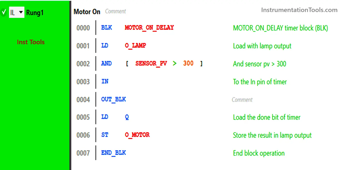
See the second rung written. Here, we first use a timer block of TON named motor_on_delay. BLK stands for block, IN is the input pin of the block, and END_BLK denotes the end of block operation. So, the sequence is like – if the lamp is on and the sensor value is more than 300, the timer turns on. The done bit of the timer (Q) is used to turn on the motor coil.
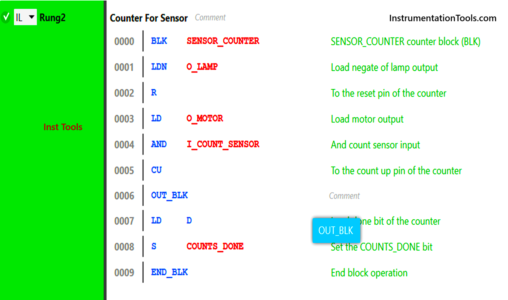
See the third rung written. Here, we first use a counter block named sensor_counter. LDN is a normal NC element, R is the reset pin of the block, CU is the count up pin of the block and S is a set coil. So, the sequence is like – if the lamp is off, then the counter will be reset. If the motor is on and the count sensor is sensing, the counter will increment till 10. The output bit (D) of the counter will be used to set a bit named counts_done.
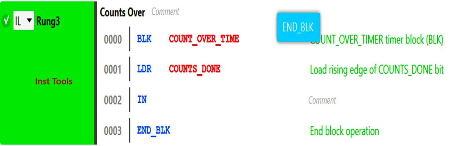
See the fourth rung written. Here, we first use a timer block of TP named count_over_time. LDR stands for rising edge pulse contact. So, the sequence is like – If the positive edge of counts_done bit is received, then the pulse timer of 1 second starts. This bit is used further in the first rung to cut off the lamp output.
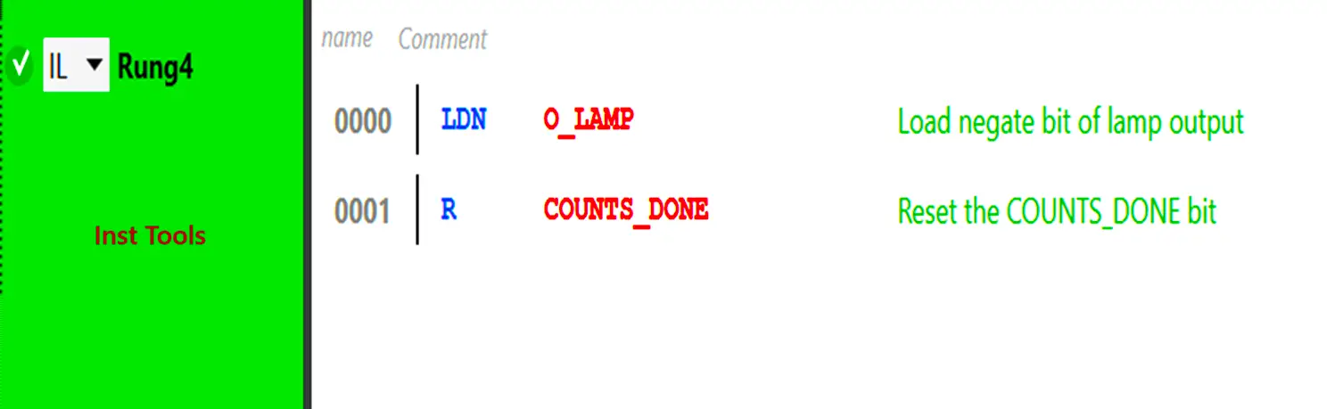
See the last rung written. R stands for reset coil. So, the sequence is like – If the lamp is off, then the bit counts_done is reset.
Instruction list is thus a series of instructions written one in each line. In this way, we saw a sample of how to write basic instructions using instruction list language.
Read Next:
- Light Sequences Structured Text PLC Program
- Explain the Operation of the Lamp Circuit
- Simple Conveyor Control PLC Program Example
- PLC Sequential Control of Three Lights with Reset
- Basic PLC Conveyor System for Product Handling