When a motor is rotated in a forward or reverse direction, care must be taken electrically too. Otherwise, the motor can be damaged. So, limit switches or encoders are installed in many systems to prevent the motor from getting damaged. Also, various factors like speed, acceleration time, and deceleration time play an important role. For this purpose, I have chosen this simple yet critical topic to write a PLC program. In this post, we will see how to write a PLC program for motor forward and reverse direction using instruction list language.
PLC Instruction List for Motor
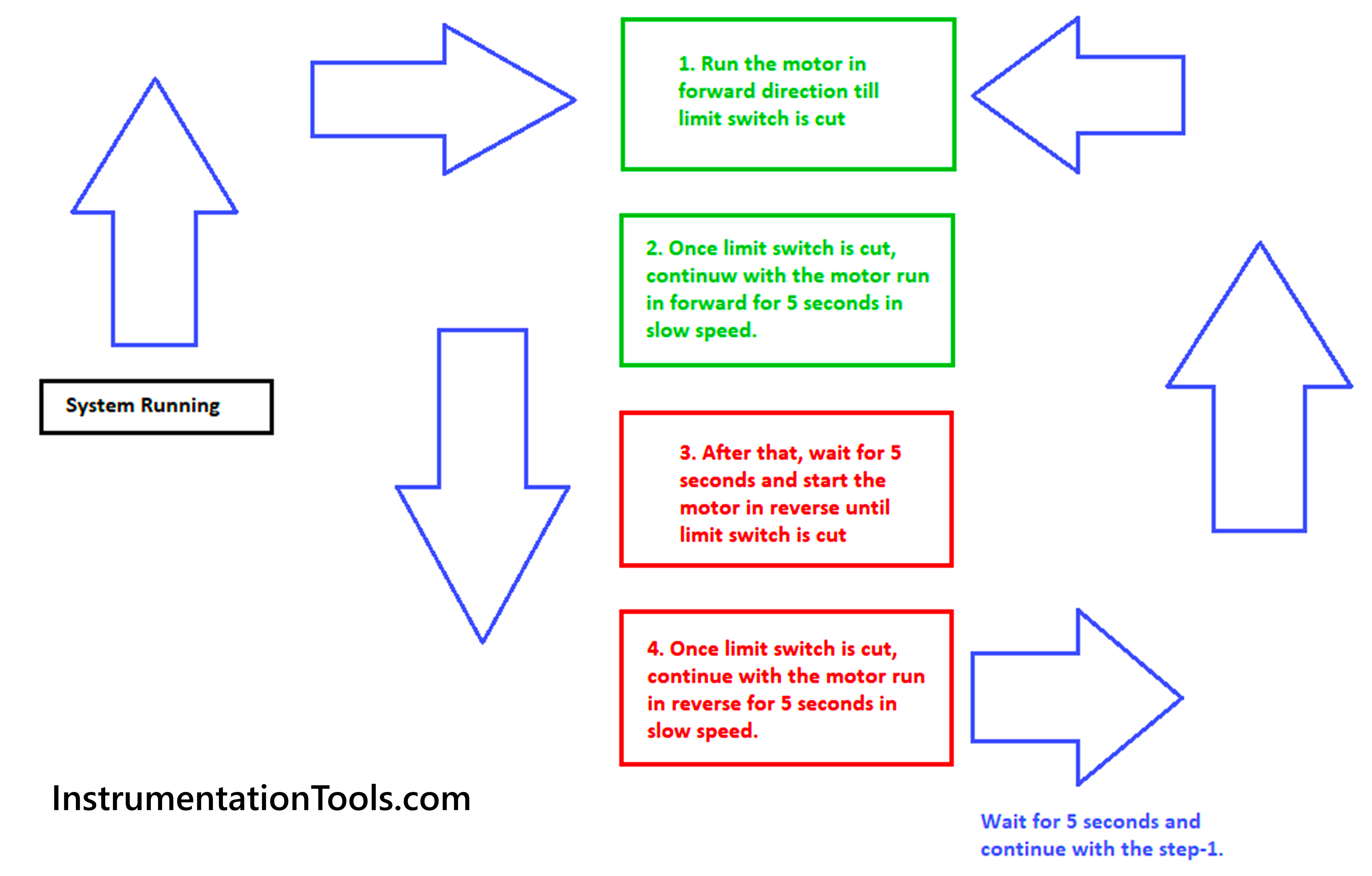
Let us understand the case scenario first. We have a motor which can rotate in both the forward and reverse directions. When the motor is started, it moves at a slow speed for 5 seconds, then to full speed (in forward direction).
The motor is moving a load and when that load touches a limit switch, it again moves at a slow speed for 5 seconds and then stops. It then moves in reverse direction after 5 seconds. It moves at a slow speed for 5 seconds, then to full speed. The motor is moving a load and when that load touches a limit switch, it again moves at a slow speed for 5 seconds and then stops. The cycle repeats again.
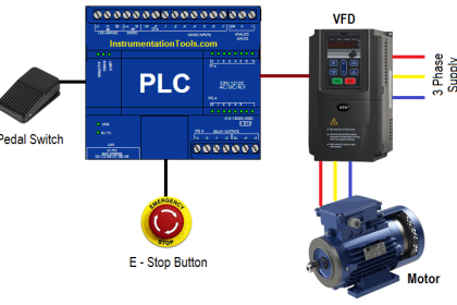
We will write this logic using Machine Expert Basic software. The language used will be an instruction list. The following are the PLC inputs – forward limit switch and reverse limit switch. The following are the PLC outputs – motor forward and motor reverse.
Motor Reverse and Forward Direction Control
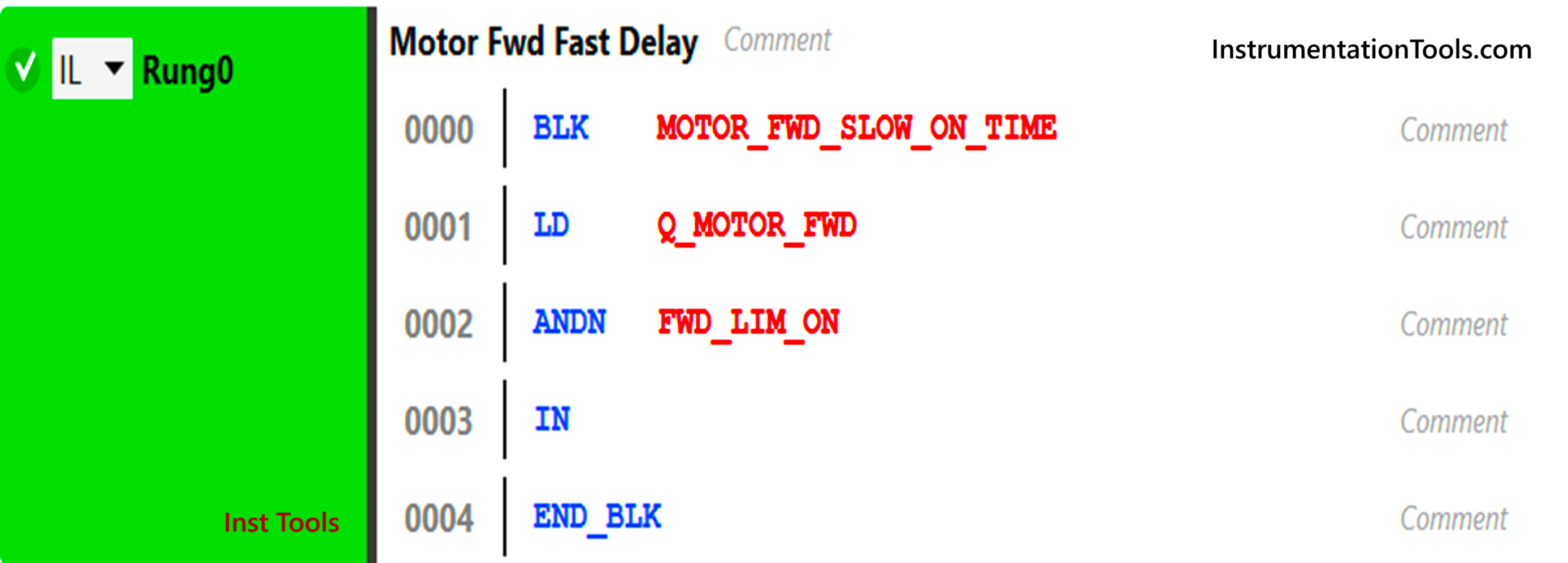
Refer to the first rung below. The mnemonics used are – BLK (timer block), LD (NO contact), ANDN (and condition in negate way), and END_BLK (end of timer instruction). So, the sequence works as – if the motor is on in forward direction and forward limit has not been cut, then a timer of 5 seconds will run and after that, a full speed will be moved in the motor frequency. Before this time, the motor will run at slow speed.
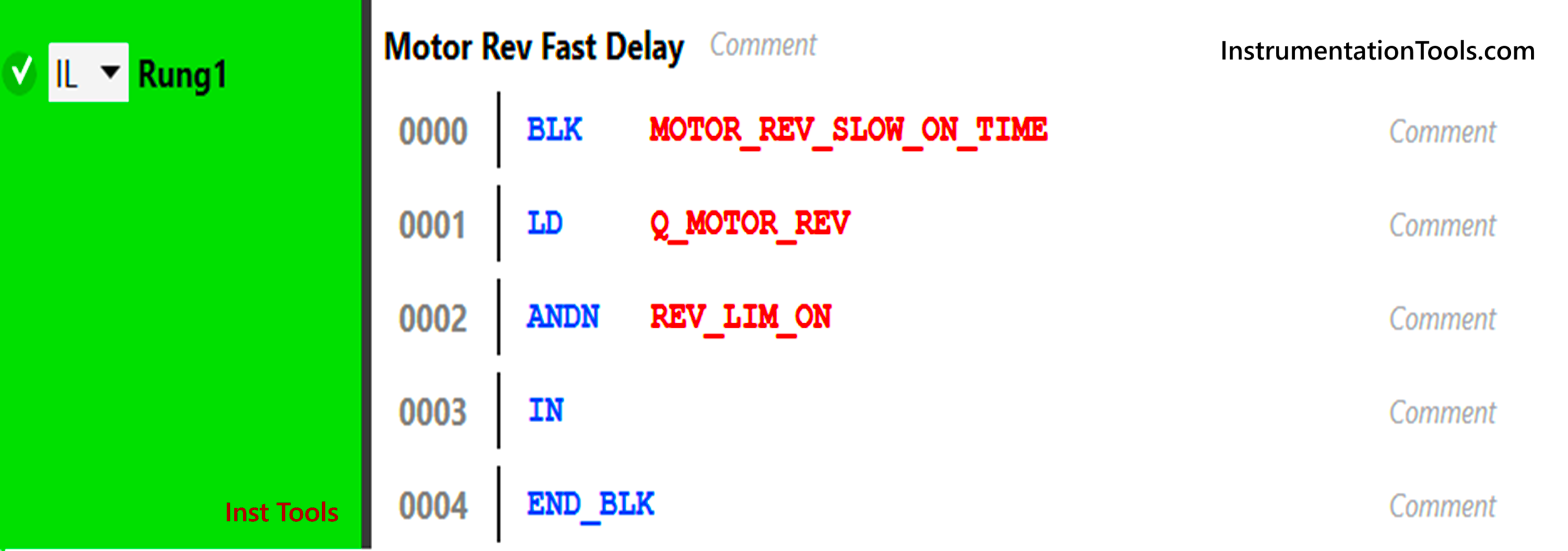
Refer to the second rung below. The mnemonics used are – BLK (timer block), LD (NO contact), ANDN (and condition in negate way), and END_BLK (end of timer instruction). So, the sequence works as – if the motor is on in reverse direction and reverse limit has not been cut, then a timer of 5 seconds will run and after that, a full speed will be moved in the motor frequency. Before this time, the motor will run at slow speed.
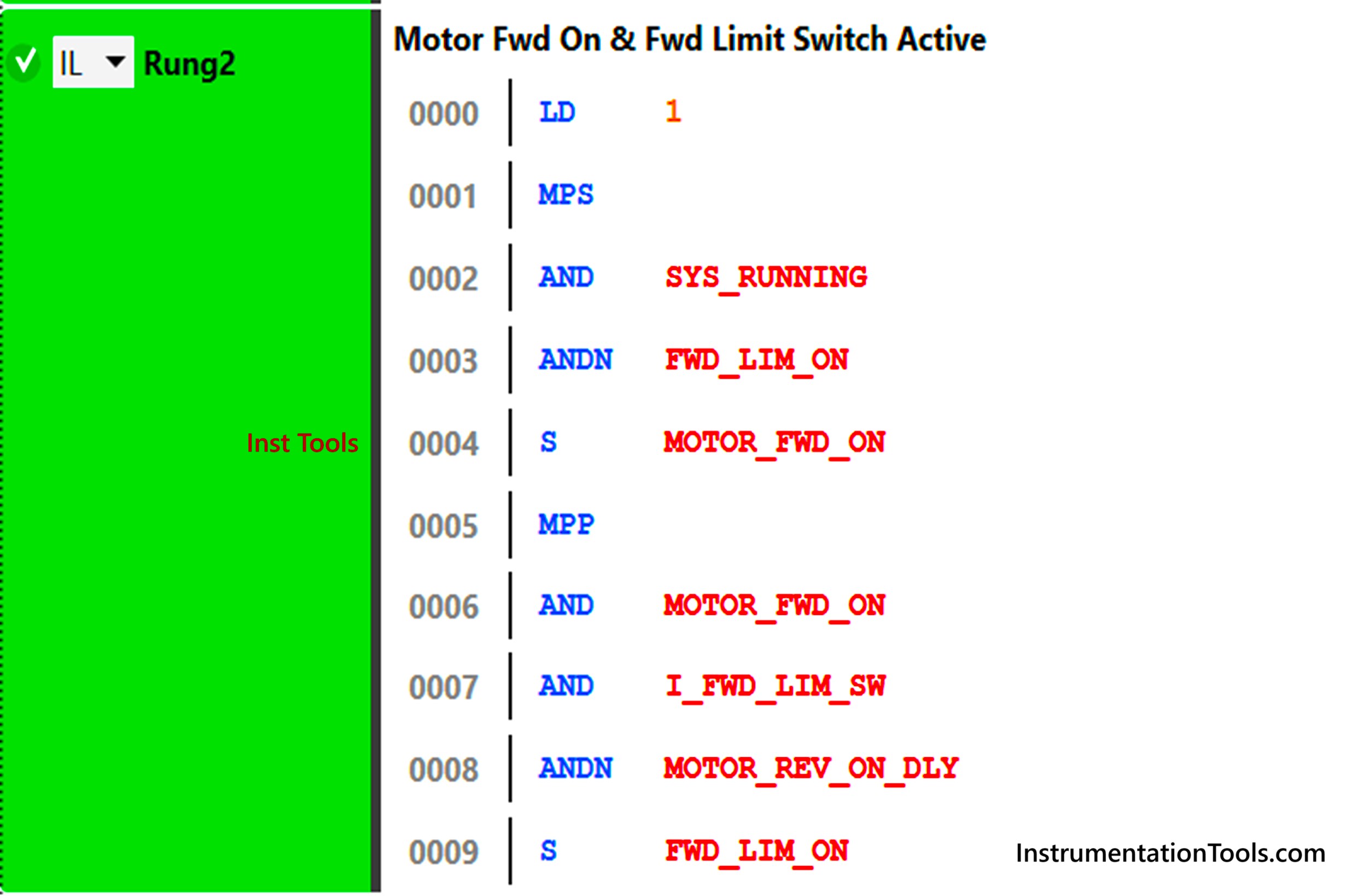
Refer to the third rung below. The mnemonics used are – MPS (branch start), AND (and condition), ANDN (and condition in negate way), S (set coil), and MPP (branch end). So, the sequence works as in the first branch – if the system is running and the forward limit has not been cut, then the motor will run in forward direction. The sequence works as in the second branch – if the motor is running forward and the forward limit has been cut and motor reverse on delay has not been started, then too the motor will run in forward direction.
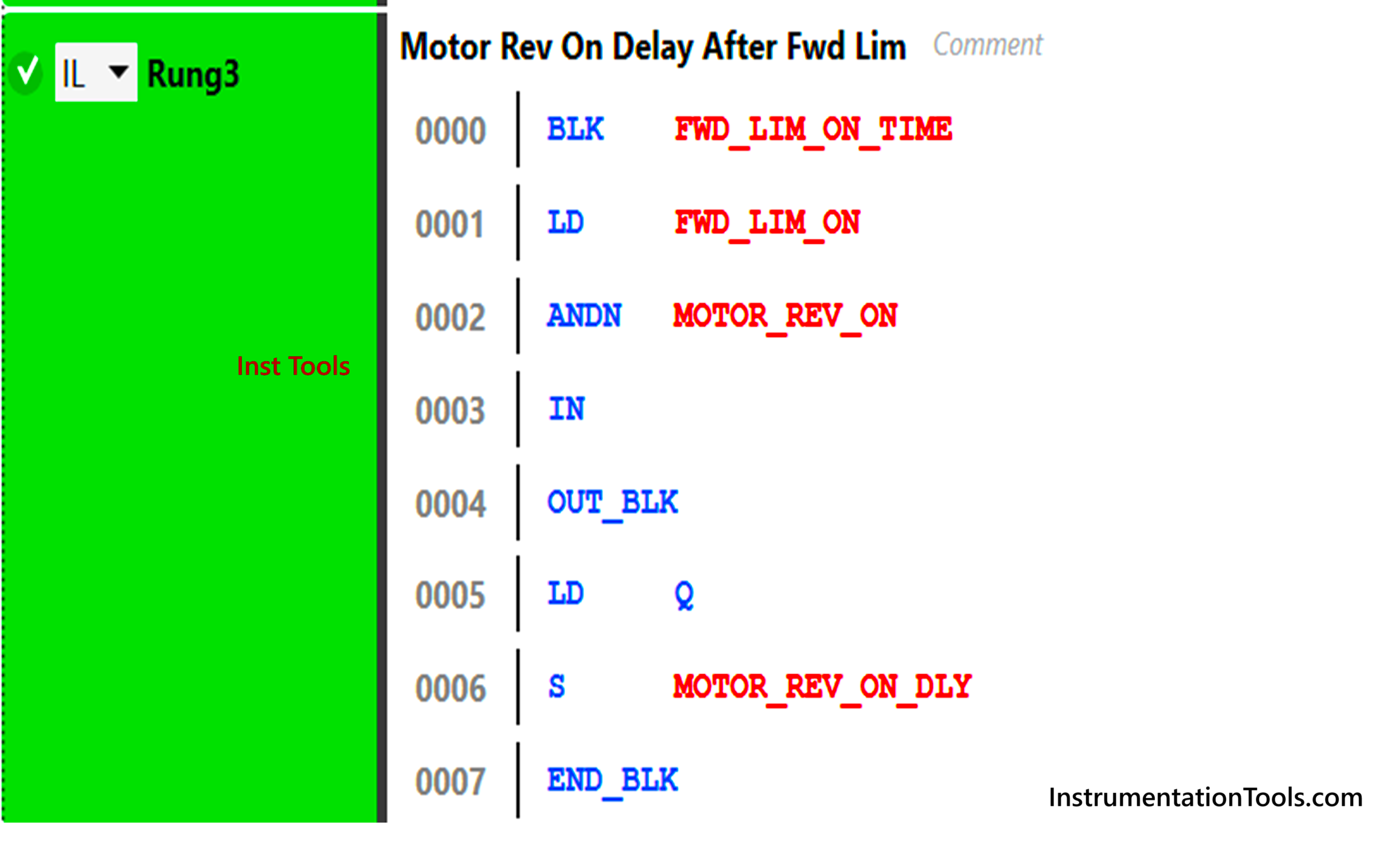
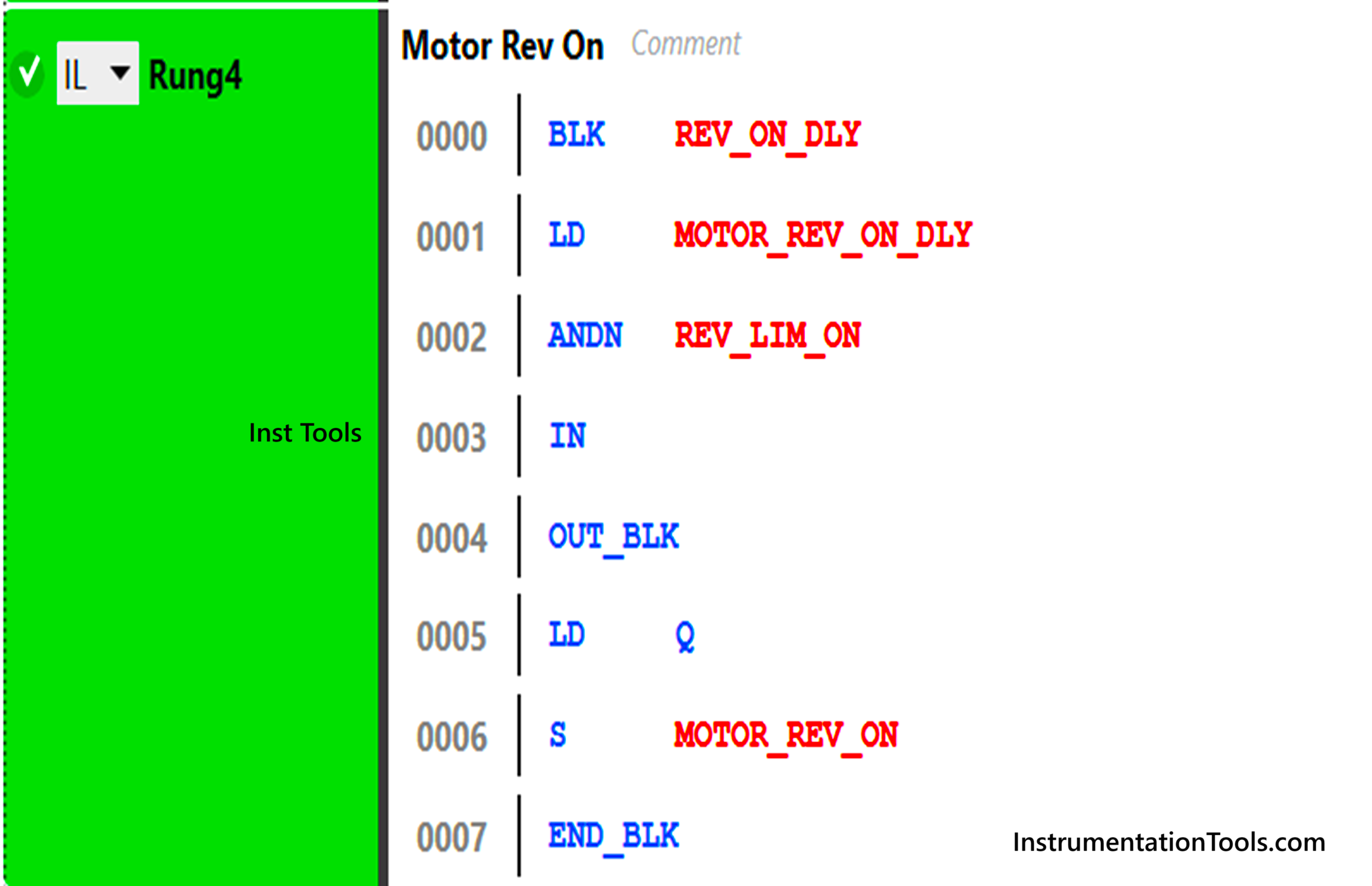
Refer to the fourth rung below. The mnemonics used are – BLK (timer block), LD (NO contact), ANDN (and condition in negate way), S (set coil) and END_BLK (end of timer instruction). So, the sequence works as – if the forward limit has been cut and the motor reverse has not been started, then a timer of 5 seconds will run and after that, the motor reverse on delay will start.
Refer to the fifth rung below. The mnemonics used are – BLK (timer block), LD (NO contact), ANDN (and condition in negate way), S (set coil) and END_BLK (end of timer instruction). So, the sequence works as – if the motor reverse delay has started and the reverse limit has not been cut, then a timer of 5 seconds will start and after that, the motor will run in reverse direction.
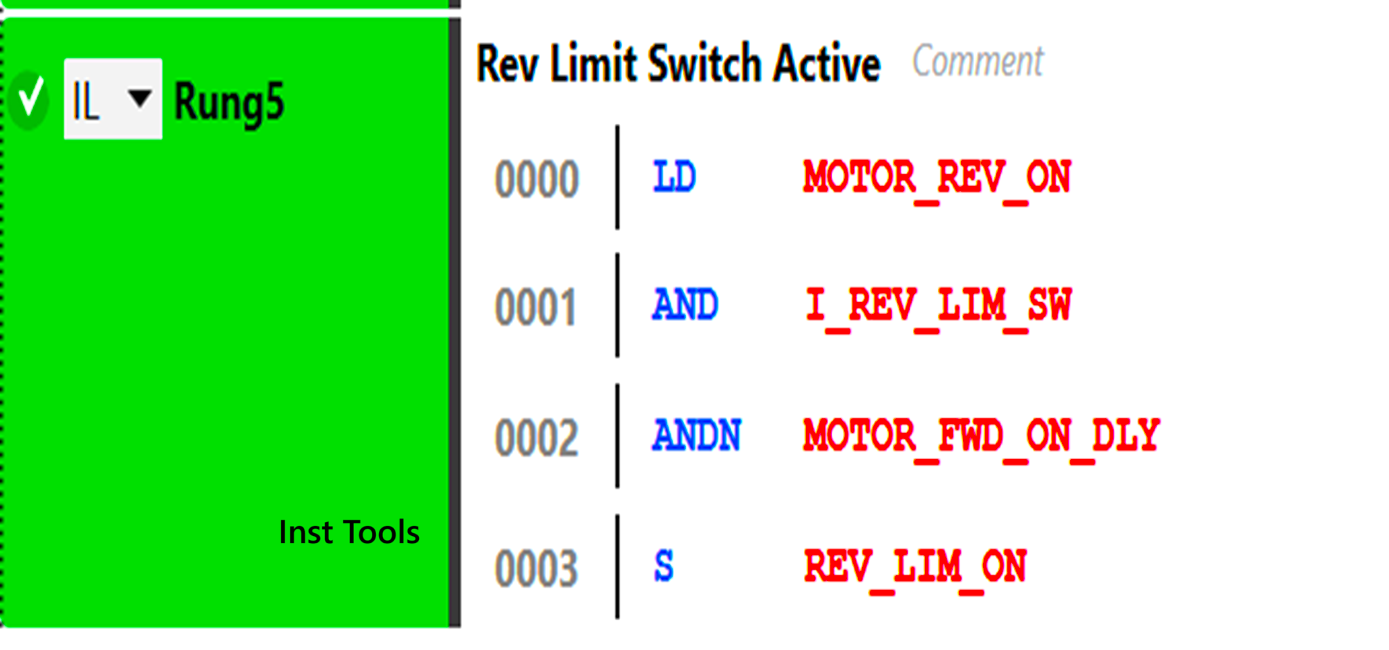
Refer to the sixth rung below. The mnemonics used are – LD (NO contact), ANDN (and condition in negate way), S (set coil) and AND (and condition). So, the sequence works as – if the motor is on in reverse direction, and the reverse limit has been cut and the motor forward delay has not been started, then too the motor will run in reverse direction.
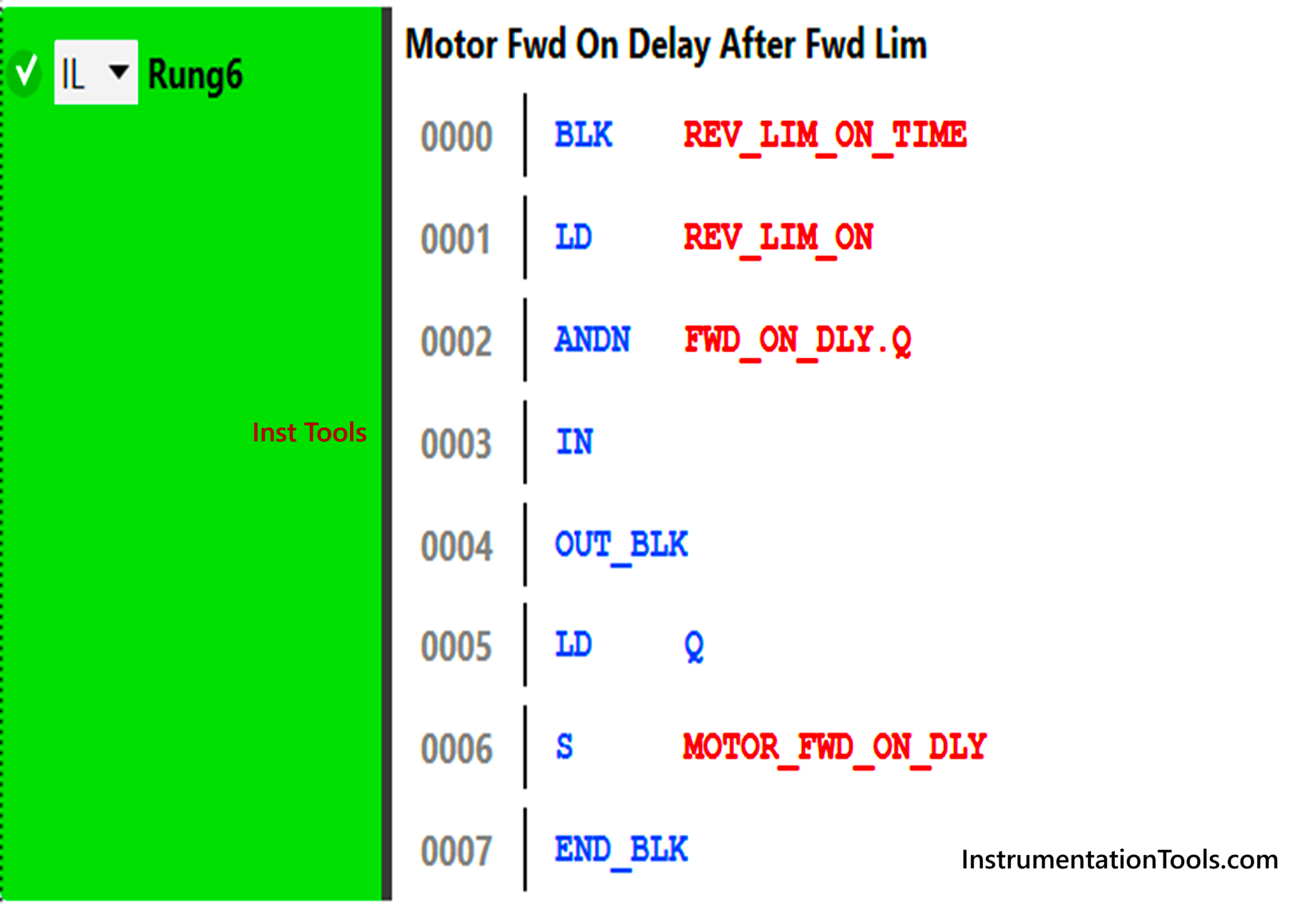
Refer to the seventh rung below. The mnemonics used are – BLK (timer block), LD (NO contact), ANDN (and condition in negate way), S (set coil) and END_BLK (end of timer instruction). So, the sequence works as – if the reverse limit has been cut and the motor forward has not been started, then a timer of 5 seconds will run and after that, the motor forward on delay will start.
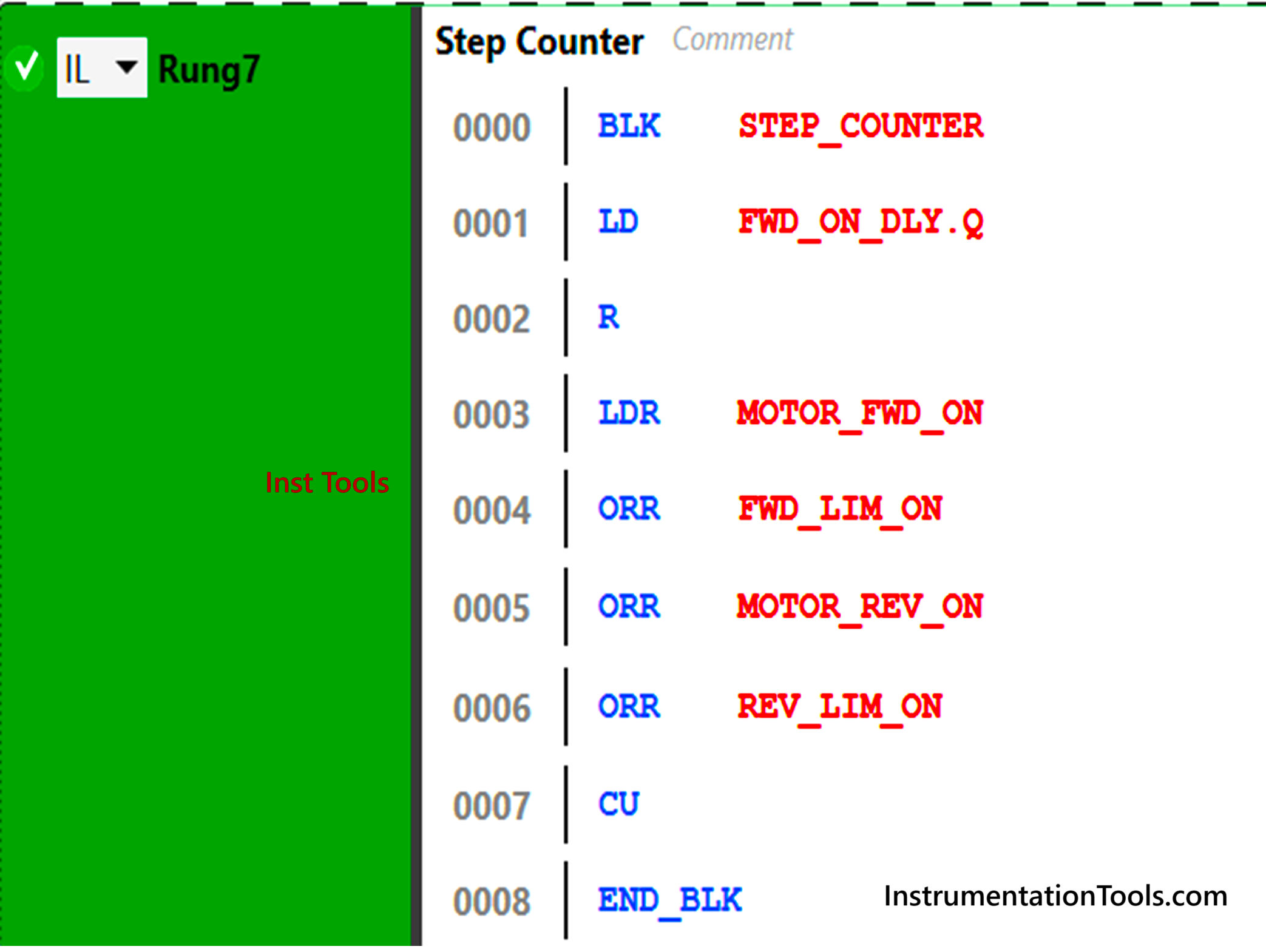
Refer to the eighth rung below. The mnemonics used are – BLK (counter block), LD (NO contact), R (reset pin), LDR (rising edge contact), ORR (or condition with rising edge contact), CU (count up pin) and END_BLK (end of counter instruction). So, the sequence works as -whenever a new command for motor run has been triggered (not motor delay), the counter will increment till 5. The counter will reset in the last step when the motor forward has started once again.
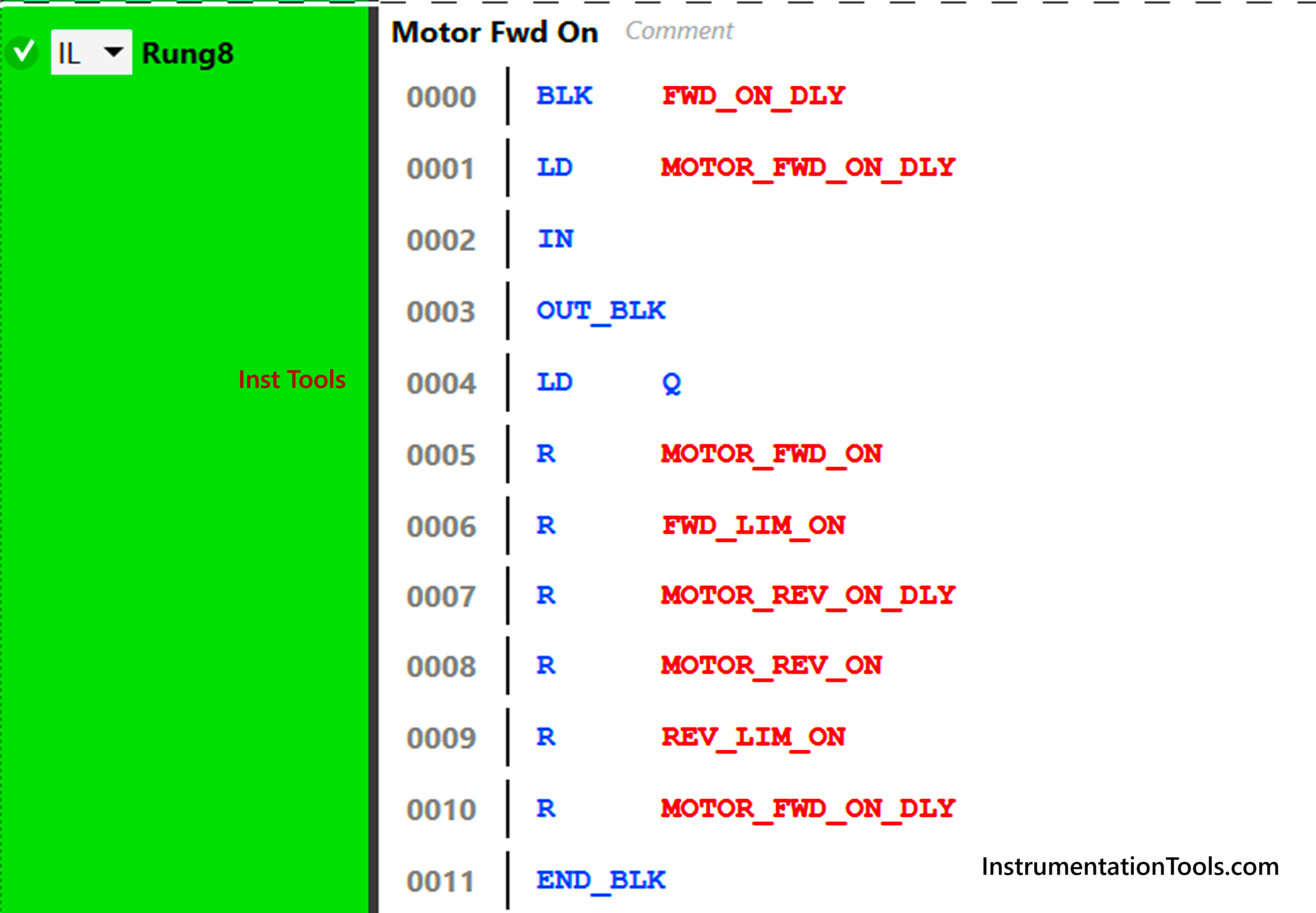
Refer to the ninth rung below. The mnemonics used are – BLK (timer block), LD (NO contact), R (reset coil) and END_BLK (end of timer instruction). So, the sequence works as – if the motor forward delay has started, then a timer of 5 seconds will run and after that, all the bits will be reset and the cycle will continue once again.
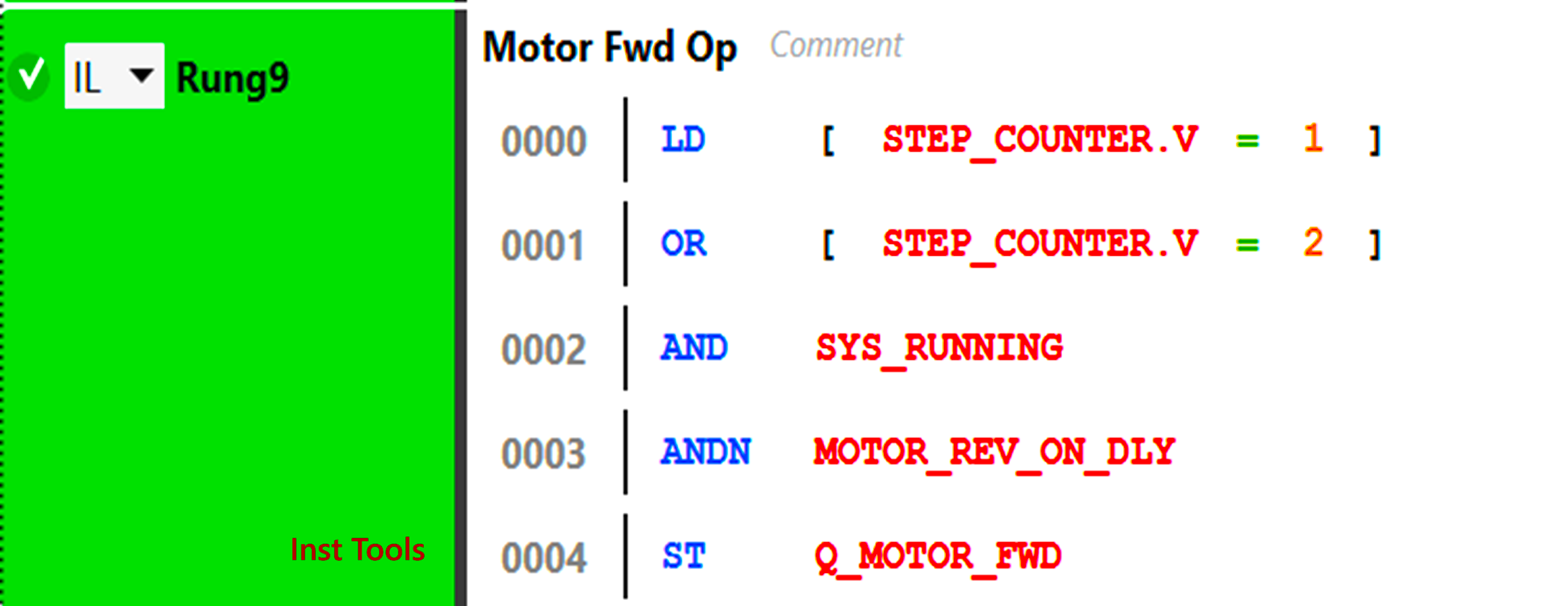
Refer to the tenth rung below. The mnemonics used are – R (or condition), LD (NO contact), AND (and condition), ANDN (and condition in negate way) and ST (normal coil). So, the sequence works as – if the current counter value is 1 or 2, and the system is running, and motor reverse delay has not started, then the motor will run in forward direction.
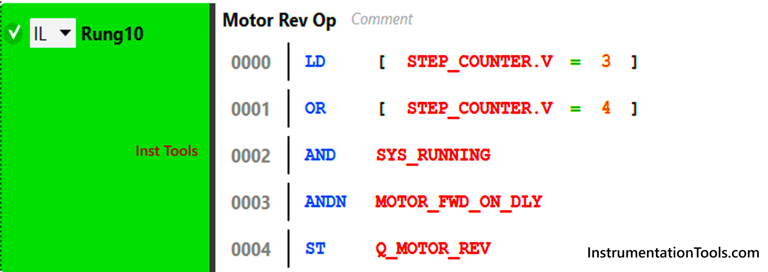
Refer to the 11th rung below. The mnemonics used are – R (or condition), LD (NO contact), AND (and condition), ANDN (and condition in negate way) and ST (normal coil). So, the sequence works as – if the current counter value is 3 or 4, and the system is running, and motor forward delay has not started, then the motor will run in reverse direction.
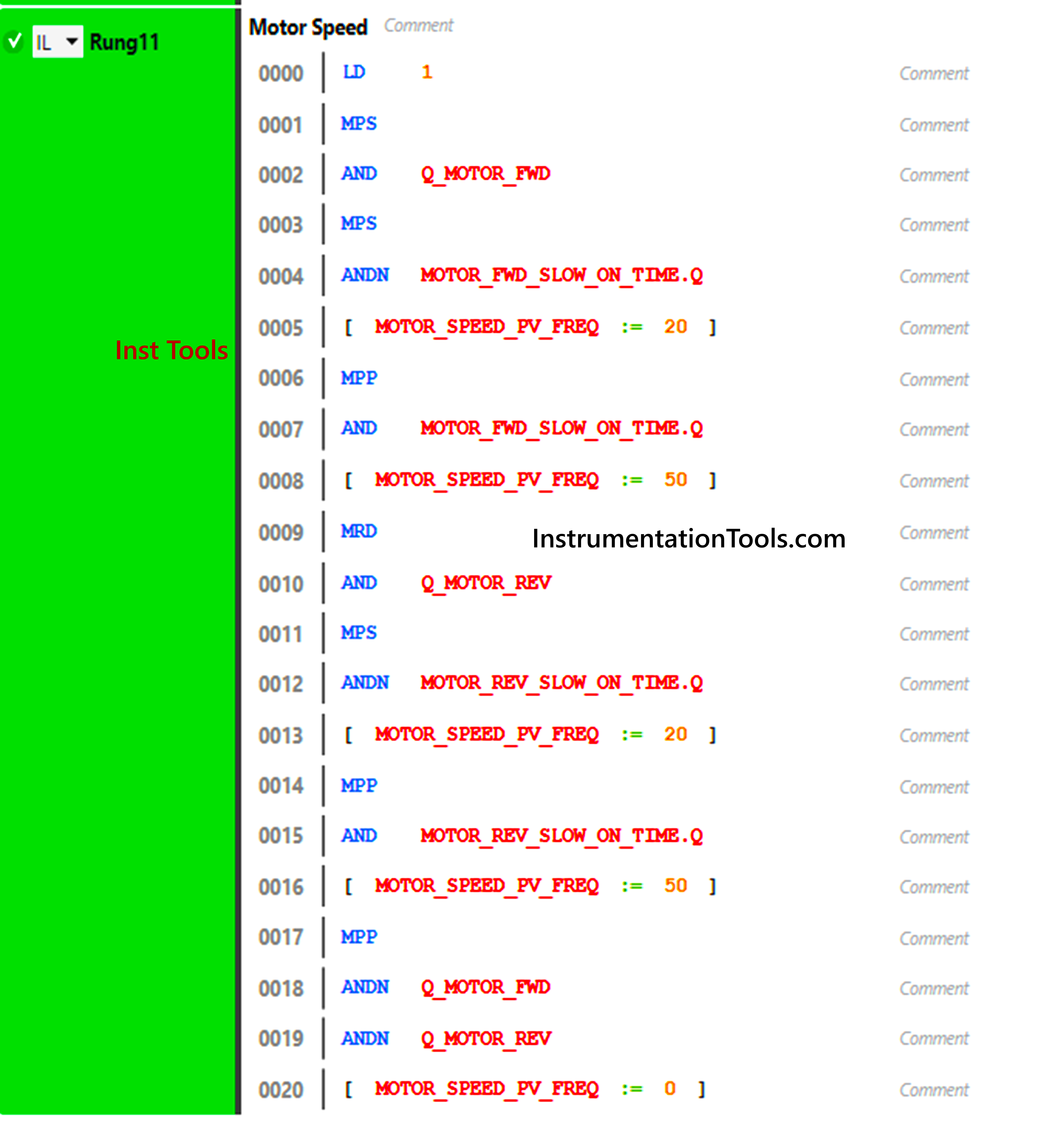
Refer to the 12th rung below. The mnemonics used are – MPS (branch start), AND (and condition), ANDN (and condition in negate way), MRD (branch extension), and MPP (branch end). So, the sequence works as in the first branch – if the motor is on in forward direction and the fast delay has not been completed, then 20 hz will be moved; otherwise 50 hz will be moved. The sequence works as in the second branch – if the motor is on in reverse direction and the fast delay has not been completed, then 20 hz will be moved; otherwise 50 hz will be moved. The sequence works as in the third branch – if the motor is off in both the directions, then 0 hz will be moved.
In this way, we saw how to write a motor forward and reverse direction using an instruction list. Refer to the below image for more understanding.
Read Next:
- Light Sequences Structured Text PLC Program
- Schneider Electric PLC Problem Vacuum Cleaner
- Motor Direction Control using Limit Switches
- Star Delta Starter using Functional Block Diagram
- While Do Statement in Structured Text PLC Program