Inst ToolsInst ToolsInst Tools
  • Courses
  • Automation
    • PLC
    • Control System
    • Safety System
    • Communication
    • Fire & Gas System
  • Instrumentation
    • Design
    • Pressure
    • Temperature
    • Flow
    • Level
    • Vibration
    • Analyzer
    • Control Valve
    • Switch
    • Calibration
    • Erection & Commissioning
  • Interview
    • Instrumentation
    • Electrical
    • Electronics
    • Practical
  • Q&A
    • Instrumentation
    • Control System
    • Electrical
    • Electronics
    • Analog Electronics
    • Digital Electronics
    • Power Electronics
    • Microprocessor
  • Request
Search
  • Books
  • Software
  • Projects
  • Process
  • Tools
  • Basics
  • Formula
  • Power Plant
  • Root Cause Analysis
  • Electrical Basics
  • Animation
  • Standards
  • 4-20 mA Course
  • Siemens PLC Course
Reading: PLC Analog Input Conversion Formula
Share
Font ResizerAa
Inst ToolsInst Tools
Font ResizerAa
  • Courses
  • Design
  • PLC
  • Interview
  • Control System
Search
  • Courses
  • Automation
    • PLC
    • Control System
    • Safety System
    • Communication
    • Fire & Gas System
  • Instrumentation
    • Design
    • Pressure
    • Temperature
    • Flow
    • Level
    • Vibration
    • Analyzer
    • Control Valve
    • Switch
    • Calibration
    • Erection & Commissioning
  • Interview
    • Instrumentation
    • Electrical
    • Electronics
    • Practical
  • Q&A
    • Instrumentation
    • Control System
    • Electrical
    • Electronics
    • Analog Electronics
    • Digital Electronics
    • Power Electronics
    • Microprocessor
  • Request
Follow US
All rights reserved. Reproduction in whole or in part without written permission is prohibited.
Inst Tools > Blog > Formulas > PLC Analog Input Conversion Formula

PLC Analog Input Conversion Formula

Last updated: March 4, 2021 4:18 pm
Editorial Staff
Formulas PLC Tutorials
2 Comments
Share
3 Min Read
SHARE

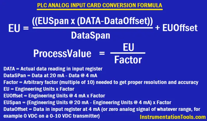
For any unit conversion on any PLC, you can use four function math with the following for PLC Analog Input Conversion Formula, which assumes integer math, as follows :

PLC Conversion Formula
PLC Analog Input Conversion Formula

Formulas:

EU = ((EUSpan x (DATA – DataOffset))/DataSpan) + EUOffset

ProcessValue = EU / FACTOR

DataOffset = Data in input register at 4 mA (or zero analog signal of whatever range – for example 0 VDC on a 0-10 VDC transmitter)

DataSPan = Data at 20 mA – Data @ 4 mA

FACTOR = arbitrary factor (multiple of 10) needed to get proper resolution and accuracy

EU = Engineering Units x FACTOR

EUOffset = Engineering Units @ 4 mA x FACTOR

EUSpan = (Engineering Units @ 20 mA – Engineering Units @ 4 mA) x FACTOR

DATA = Actual data reading in input register

For Example,

A Pressure transmitter of range 0 to 60 psig is connected to an PLC analog input card. The PLC Analog input card raw count starting from 6240 for 4mA and 31208 for 20mA. PLC reading 18975 raw counts and calculate equivalent pressure transmitter reading.

Note: PLC raw counts may vary from system to system.

0-60 psig from 4-20 mA with resolution of 0.1 psig:

FACTOR = 10

Data @ 4 mA = 6240

Data @ 20 mA = 31208

DataOffset = 6240

DataSpan = 31208 – 6240 = 24968

EUOffset = 0 x 10 = 0

EUSpan = (60 – 0) x 10 = 600

DATA = 18975

EU = ((EUSpan x (DATA – DataOffset))/DataSpan) + EUOffset

EU = ((600 x (18975 – 6240)) / 24968) + 0 = 306

ProcessValue = EU / FACTOR

Process Value = 306 / 10 = 30.6 psig

If you liked this article, then please subscribe to our YouTube Channel for PLC and SCADA video tutorials.

You can also follow us on Facebook and Twitter to receive daily updates.

Read Next:

Process Interlocks and Trips

Split Range Control Loop

Analyze a Cascade Control Loop
Ratio Controller Example

PID Tuning Procedure

Don't Miss Our Updates
Be the first to get exclusive content straight to your email.
We promise not to spam you. You can unsubscribe at any time.
Invalid email address
You've successfully subscribed !

Continue Reading

Free Allen Bradley PLC Ladder Logic Training Course
Count the Number of Cartons in a Storage Area PLC Logic
Types of SCADA System Architecture
PLC Logic GATE Program
How to Create Templates in FactoryTalk View Studio?
Workstation Healthiness Checks
Share This Article
Facebook Whatsapp Whatsapp LinkedIn Copy Link
Share
2 Comments
  • kingsley says:
    September 14, 2016 at 12:40 pm

    NICE ONE SIR,

    I APPRECIATE THIS

    Reply
  • jignesh says:
    November 26, 2016 at 1:17 pm

    thank you so much sir..Its a very useful things..your work is really very good..

    Reply

Leave a Reply Cancel reply

Your email address will not be published. Required fields are marked *

Stay Connected

128.3kFollowersLike
69.1kFollowersFollow
210kSubscribersSubscribe
38kFollowersFollow

Categories

Explore More

Proper Earthing Practices Used for PLC Control Panel
Schneider Electric: Car Parking System with Calculations in PLC
How to Design an Effective HMI? – Human Machine Interface
Zero Suppression and Zero Elevation Calculations
Auto Tiffin Box Filling Station
#1 PLC Best Practices – Split PLC Code into Modules
Communication between Factory IO and Siemens Tia Portal
PLC based Door Open and Closing System

Keep Learning

Digital input signals in safety circuits

1oo2 Evaluation Safety Instruction in Safety PLC

PLC Program for Automatic Heating and Mixing of Products

Heating and Mixing of Products using PLC Example Tutorial

Comparison of Control Loops - Open, Closed, Cascade, Feedforward, Ratio

Comparison of Control Loops – Open, Closed, Cascade, Feedforward, Ratio

Basics of Motion Controllers

Basics of Motion Controllers

Start Stop of one Motor from same Push button PLC program

Start Stop of one Motor from the same Push button PLC program

Types of Scan Time in a PLC

#16 PLC Best Practices – Create Trend for Cycle Time on HMI

OB and FB Blocks in Siemens PLC

Procedure for Siemens S7-300 Download from PC to PLC

Difference between Signal Cables and Control Cables

Difference between Signal Cables and Control Cables

Learn More

PLC Ladder Logic Simulator Mobile Apps For Android

PLC Ladder Logic Simulator Mobile Apps For Android

Galileo thermometer Principle

Galileo Thermometer

GSD File installation in Simatic Manager

How to Install GSD File in Step 7 PLC using Simatic Manager?

progressively sequenced control valves

Progressive Control Valve Sequence

Modbus

Modbus : History, Structure, Modes, Addressing, Functions

Boiler Level Switch

Float level switch Principle

11 KV Bus A to Bus B Phase Check Problem

11 KV Bus A to Bus B Phase Check Problem

Difference between BDV and PSV

Difference between BDV and PSV

Menu

  • About
  • Privacy Policy
  • Copyright

Quick Links

  • Learn PLC
  • Helping Hand
  • Part Time Job

YouTube Subscribe

Follow US
All rights reserved. Reproduction in whole or in part without written permission is prohibited.
Welcome Back!

Sign in to your account

Username or Email Address
Password

Lost your password?