Erection & Commissioning

P&ID Guidelines for Pumps Heat Exchangers

P&ID Guidelines for Pumps Heat Exchangers

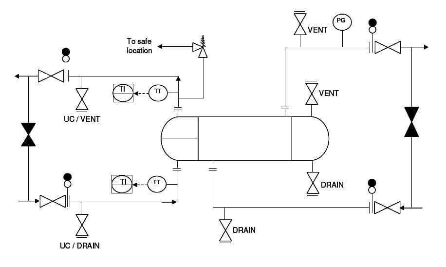
  1. Proper equipment symbol should be selected first of all, as shown in the presented drawing. This should be selected from the list of equipment symbols on the legend sheets of a particular project.
  2. All the nozzles on the exchanger should then be correctly represented with size and flanges. This includes inlet and outlet nozzles, drains, vents, utility connections etc.
  3. Inlet and outlet lines are the next to be drawn up. Line number, material class, size etc. is to be correctly assigned to each of the lines. If the unit is envisaged to be in operation while the exchanger is under maintenance, then bypass lines should be drawn up on shellside, tubeside or on both sides as shown in the drawing presented here.
  4. Isolation valves, spectacle blinds, spacers etc. to be used for maintenance should be drawn up next on the inlet / outlet lines. Bypass lines to be fitted with normally closed isolation valves.
  5. Thermal relief valve should be provided where required. Generally thermal relief valves are required on the cold liquid streams, when there is a possibility of blockage in the heating medium on the other side of exchanger. In case of such blockage, there is possibility of overheating the cold stream and hence requirement for thermal relief valve. Discharge of a relief valve to be routed to an appropriate, safe location.
  6. Drains and vents to be provided on both sides of the exchanger (hot and cold sides), either on the exchanger itself or inlet / outlet piping, so that the equipment can be completely drained for maintenance.
  7. For fouling service on the tubeside, utility connections should be provided as indicated in the presented drawing, for cleaning purpose.
  8. Temperature and pressure gauges and transmitters to be provided as per requirements for operating and controlling the equipment. Normally temperature monitoring is required for the process side of the heat exchanger. Also generally temperature control is implemented on the process side of the exchanger.
  9. All the guidelines given here are very general and may be modified as per specific requirements of any particular project.
You've successfully subscribed !
Share

Recent Articles

  • Instrumentation Design

Immersion Heaters in Lube Oil Consoles

Rotating equipment packages such as pumps, compressors, turbines need the lube oil consoles for their…

7 hours ago
  • PLC Tutorials

How to Blink Lights in Ladder Logic?

This article explains how to blink lights in ladder logic with a detailed explanation video…

3 weeks ago
  • PLC Tutorials

From Boolean Algebra to PLC Logic

In this article, a simple example will teach you the conversion from Boolean algebra to…

1 month ago
  • PLC Tutorials

PLC Cooking Timer Example for Kitchen Automation

In this article, you will learn the PLC cooking timer example for kitchen automation using…

3 weeks ago
  • PLC Tutorials

Example PLC Program to Control a Pump based on Level Sensors

Learn an example PLC program to control a pump based on level sensors using ladder…

3 weeks ago
  • PLC Tutorials

PLC Timer Application in Security Camera Recording

In the PLC timer application for security camera recording, when motion is detected then camera…

3 weeks ago