The following processes all have some problems, which may be diagnosed by careful observation of the PID controller’s faceplate display (PV, SP, and Output values) and/or indications given by gauges in the field.
Examine each control system and determine the loop faults in each one from the information given.
Assume that the conditions shown have existed for quite some time (long enough for the control system to have brought the process variable back to setpoint if everything were operating correctly):
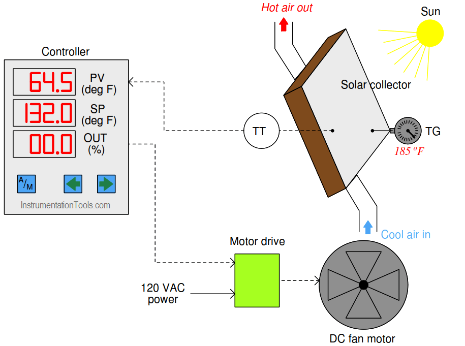
1. Solar Panel Temperature Loop
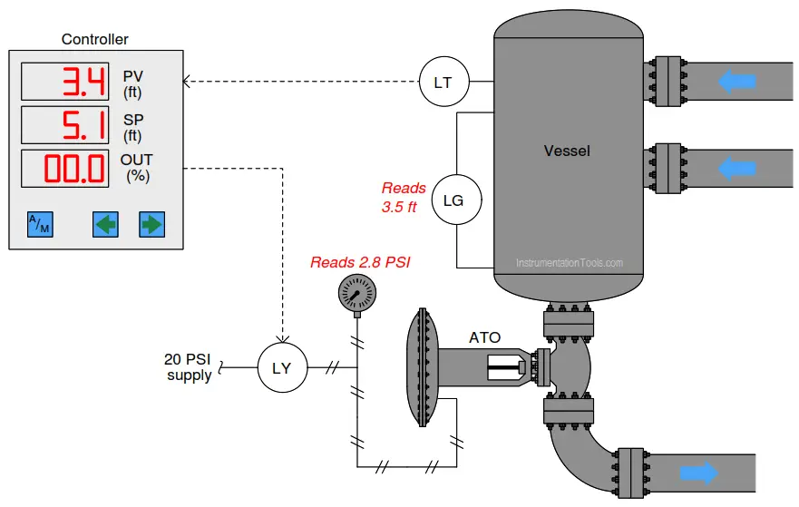
2. Level Loop
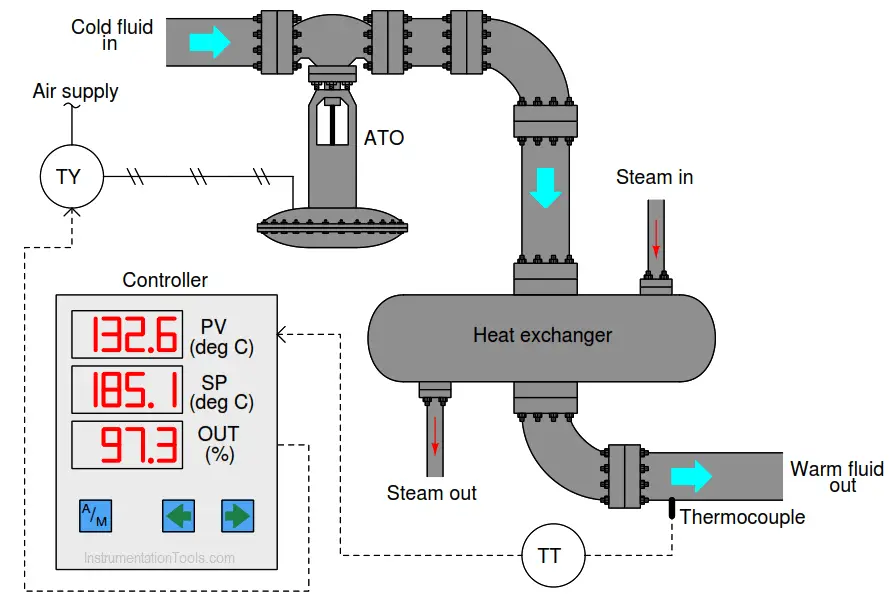
3. Heat Exchanger Loop
A valuable principle to apply in a diagnostic scenario such as this is the correspondence: identifying which values agree with each other. Explain how a check of correspondence tells us which instrument is at fault in any of these control loops.
For each of these scenarios, determine what your next diagnostic test might be to further pinpoint the location and nature of the problem.
Share your answers with us through the below comments section.
Read Next:
- PLC Troubleshooting
- Solenoid Troubleshooting
- RTD Troubleshooting
- Pressure Switch Questions
- Pneumatic Force-balance
Credits: Tony R. Kuphaldt
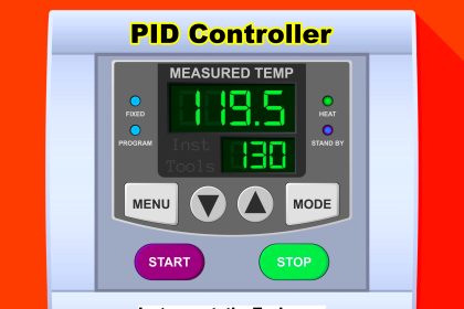


1- Wrong PV measurement. TT failure
2- There is no input flow to the tank
3- In your scenario, this has been the case for a long time. The first thing that caught my attention was that the controller output was not saturated at 0%. My guess is the controller is in p-only mode and the input and output temperatures are equal. Therefore the error remains constant and the control action is frozen at 97%. The long unresponsiveness of the controller to error can only be explained by the p-only mode.