Inst ToolsInst ToolsInst Tools
  • Courses
  • Automation
    • PLC
    • Control System
    • Safety System
    • Communication
    • Fire & Gas System
  • Instrumentation
    • Design
    • Pressure
    • Temperature
    • Flow
    • Level
    • Vibration
    • Analyzer
    • Control Valve
    • Switch
    • Calibration
    • Erection & Commissioning
  • Interview
    • Instrumentation
    • Electrical
    • Electronics
    • Practical
  • Q&A
    • Instrumentation
    • Control System
    • Electrical
    • Electronics
    • Analog Electronics
    • Digital Electronics
    • Power Electronics
    • Microprocessor
  • Request
Search
  • Books
  • Software
  • Projects
  • Process
  • Tools
  • Basics
  • Formula
  • Power Plant
  • Root Cause Analysis
  • Electrical Basics
  • Animation
  • Standards
  • 4-20 mA Course
  • Siemens PLC Course
Reading: How to Program PID Control in PLC with Structured Text?
Share
Font ResizerAa
Inst ToolsInst Tools
Font ResizerAa
  • Courses
  • Design
  • PLC
  • Interview
  • Control System
Search
  • Courses
  • Automation
    • PLC
    • Control System
    • Safety System
    • Communication
    • Fire & Gas System
  • Instrumentation
    • Design
    • Pressure
    • Temperature
    • Flow
    • Level
    • Vibration
    • Analyzer
    • Control Valve
    • Switch
    • Calibration
    • Erection & Commissioning
  • Interview
    • Instrumentation
    • Electrical
    • Electronics
    • Practical
  • Q&A
    • Instrumentation
    • Control System
    • Electrical
    • Electronics
    • Analog Electronics
    • Digital Electronics
    • Power Electronics
    • Microprocessor
  • Request
Follow US
All rights reserved. Reproduction in whole or in part without written permission is prohibited.
Inst Tools > Blog > PLC Tutorials > How to Program PID Control in PLC with Structured Text?

How to Program PID Control in PLC with Structured Text?

Learn how to control a process variable using PID in PLC with structured text. Explore the Siemens TIA Portal and write a PLC STL program.

Last updated: September 19, 2024 7:51 am
Viral Nagda
PLC Tutorials
No Comments
Share
6 Min Read
SHARE

PID is a function that is used in many PLC applications for controlling a process variable near the setpoint. If PID is configured properly and used according to the application, then we can maintain a certain process within its predefined limits.

Contents
How to Program PID Control?Structured Text PLC Program

How to Program PID Control?

For example, if we set the AC temperature to 24 deg.C, then the controller inside will maintain the current temperature near this setpoint for efficient cooling. This same function is called a PID or proportional-integral-derivative. In this post, we will see how to write a PLC program for PID using structured text in the Siemens TIA Portal.

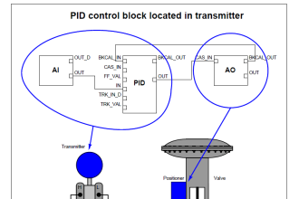
Let us understand the case scenario first. We have a flow transmitter that gives us the value of flow in a gas pipeline. The motive is to control the flow amount in the pipeline through a flow actuator valve. This valve will pass the exact amount of gas flow and control the process accordingly.

For this, we have used S7-1500 PLC and require a PID function block in this process. When the flow goes above the setpoint, the valve should close and when the flow goes below the setpoint, the valve should open. In this way, the gas flow will be maintained around the setpoint.

Structured Text PLC Program

Let us see the program below now.

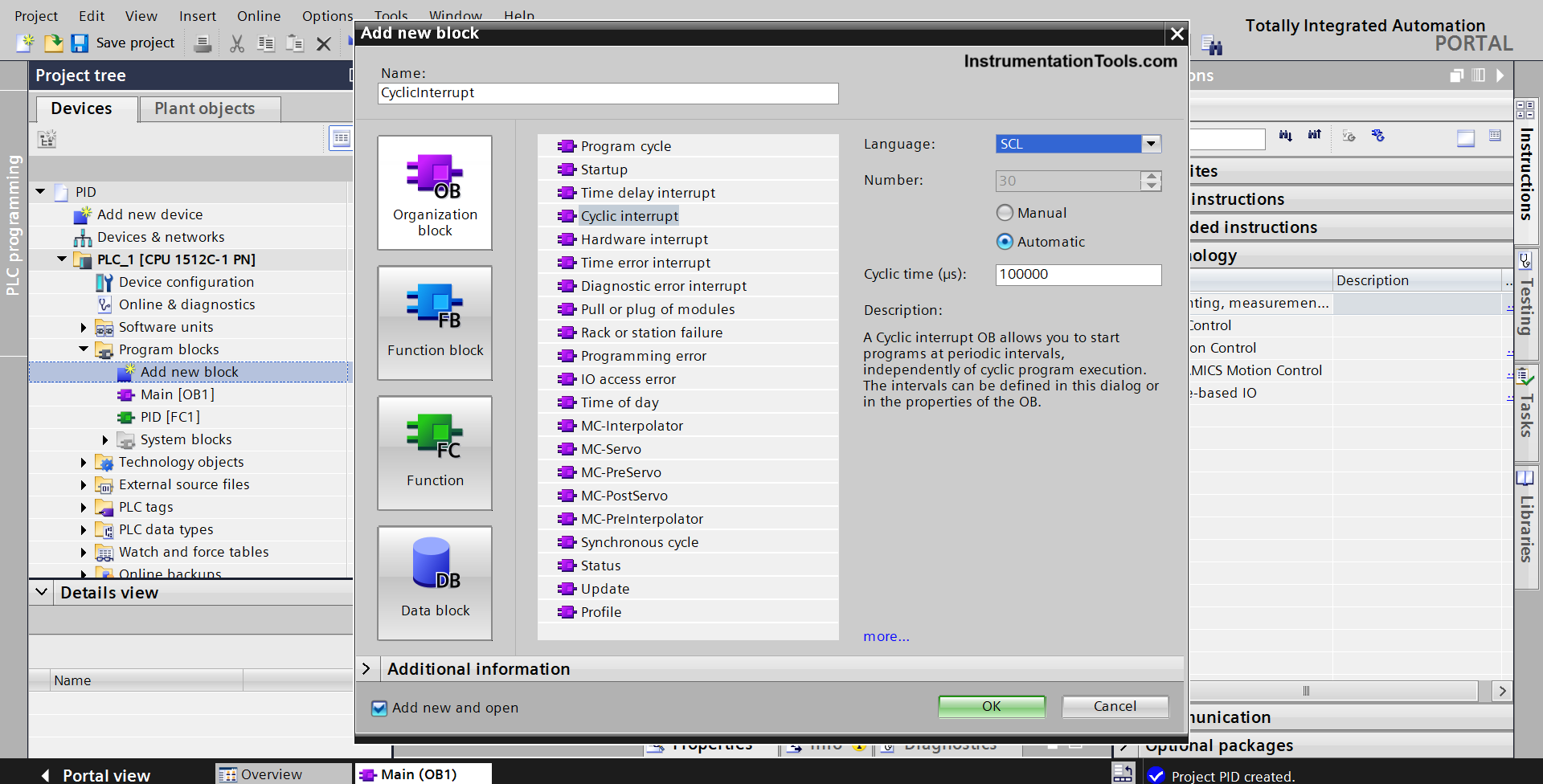
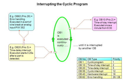
First, we need to add an OB in the program which will be a cyclic interrupt. A cyclic interrupt will trigger the function block of PID in periodic intervals, irrespective of the main program scan time.

This ensures timely action and a safe process. If we take this PID block in main program OB (also known as main OB1 in TIA Portal), then it would have been executed according to scan time; and if the program is lengthy, then it would have taken some time for the block to execute and take corrective action.

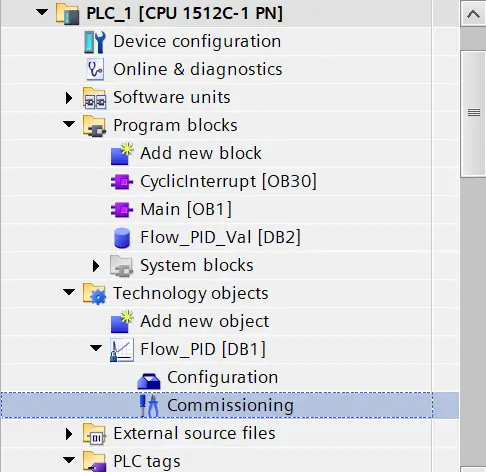
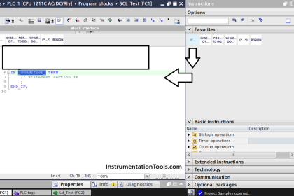
So, place this function block in cyclic interrupt OB30. Do not forget to choose the language as SCL because we are writing the program in structured text language. Refer to the below image.

PID in SCL Language

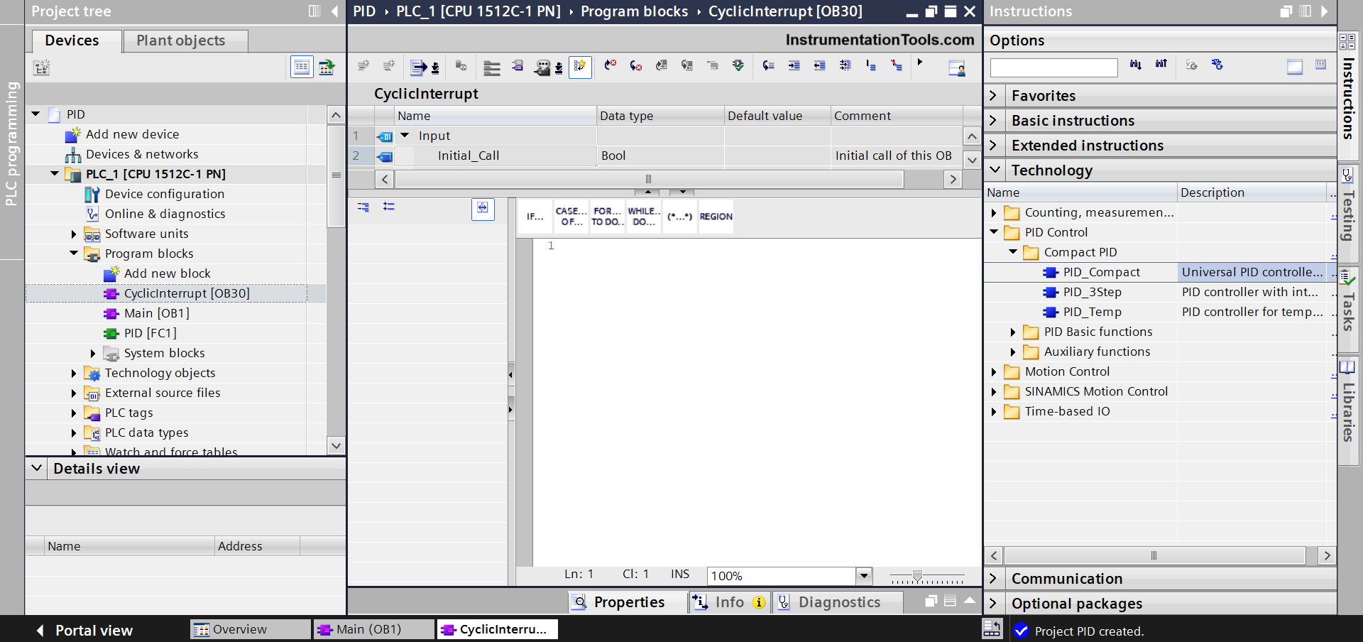
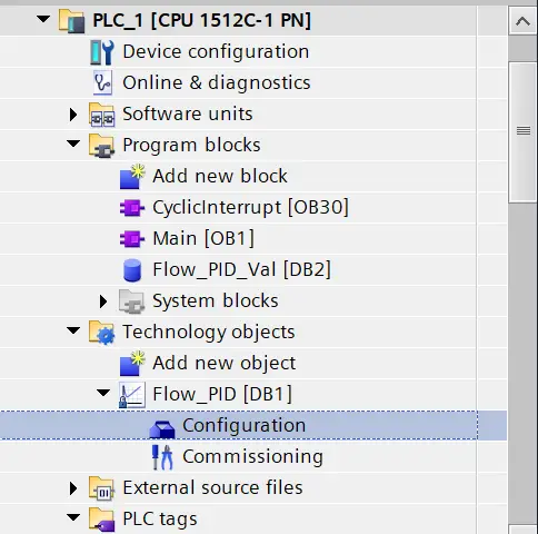
Next, you have to drag the technology object of PID as shown in the below image. Select the PID_Compact block and drag it in the OB you took earlier.

PID Compact block

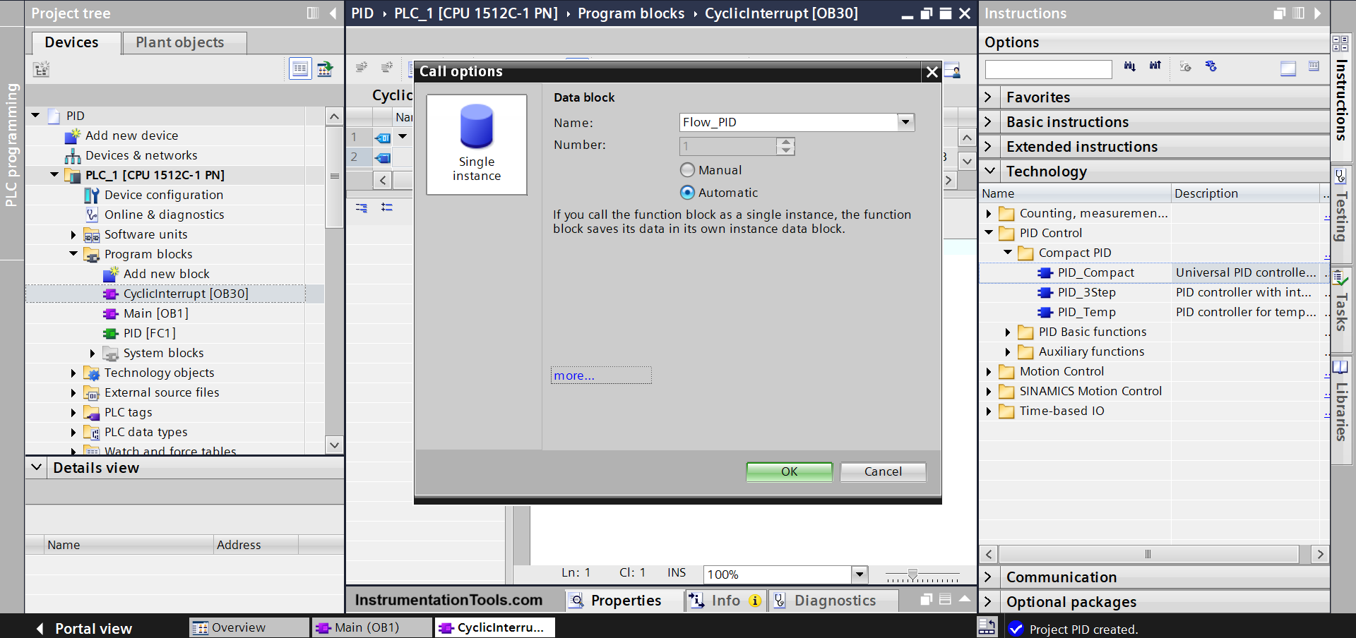
When you drag the object, you will be asked to name the instance name as shown below. Name it as Flow_PID.

Programming PID control in PLC with Structured Text

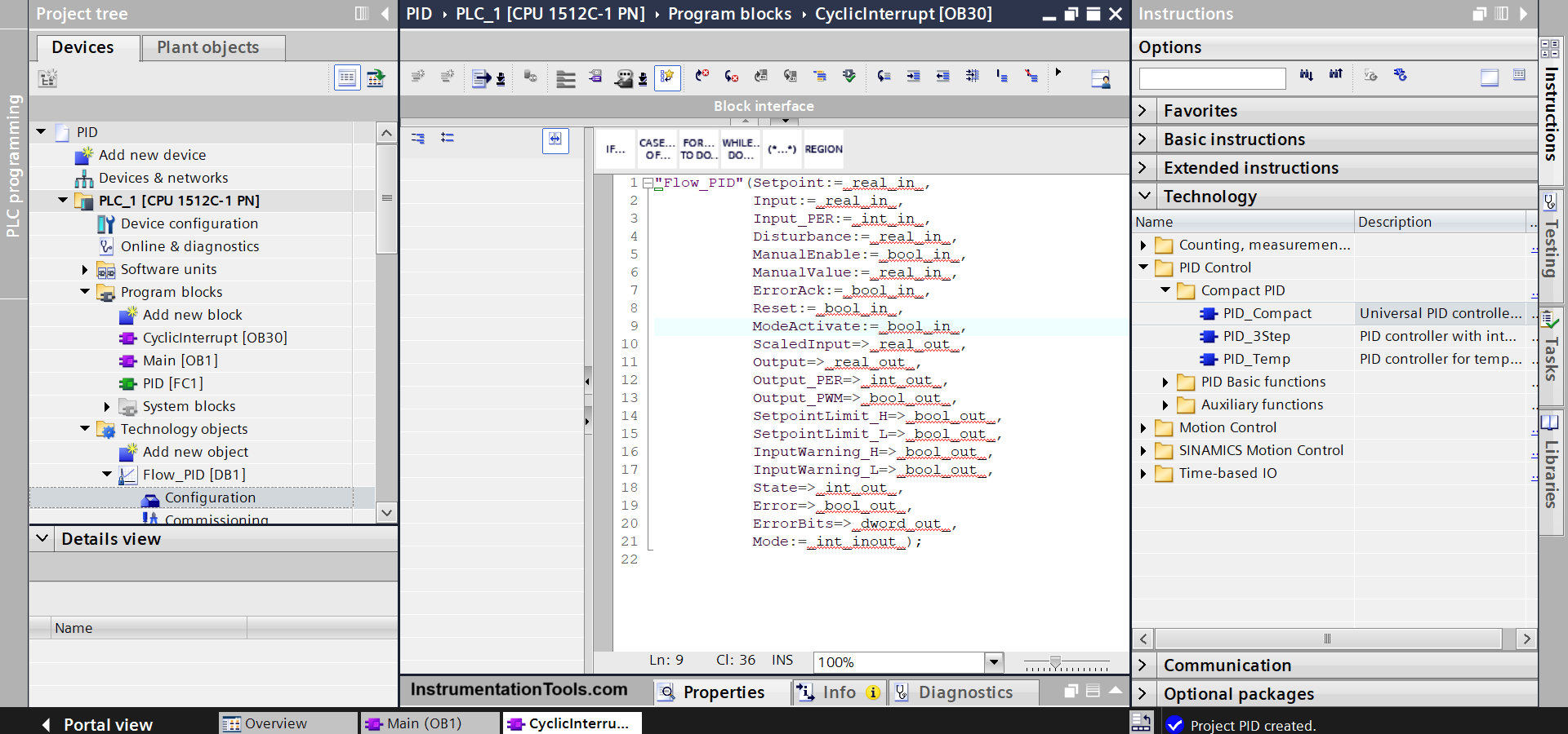
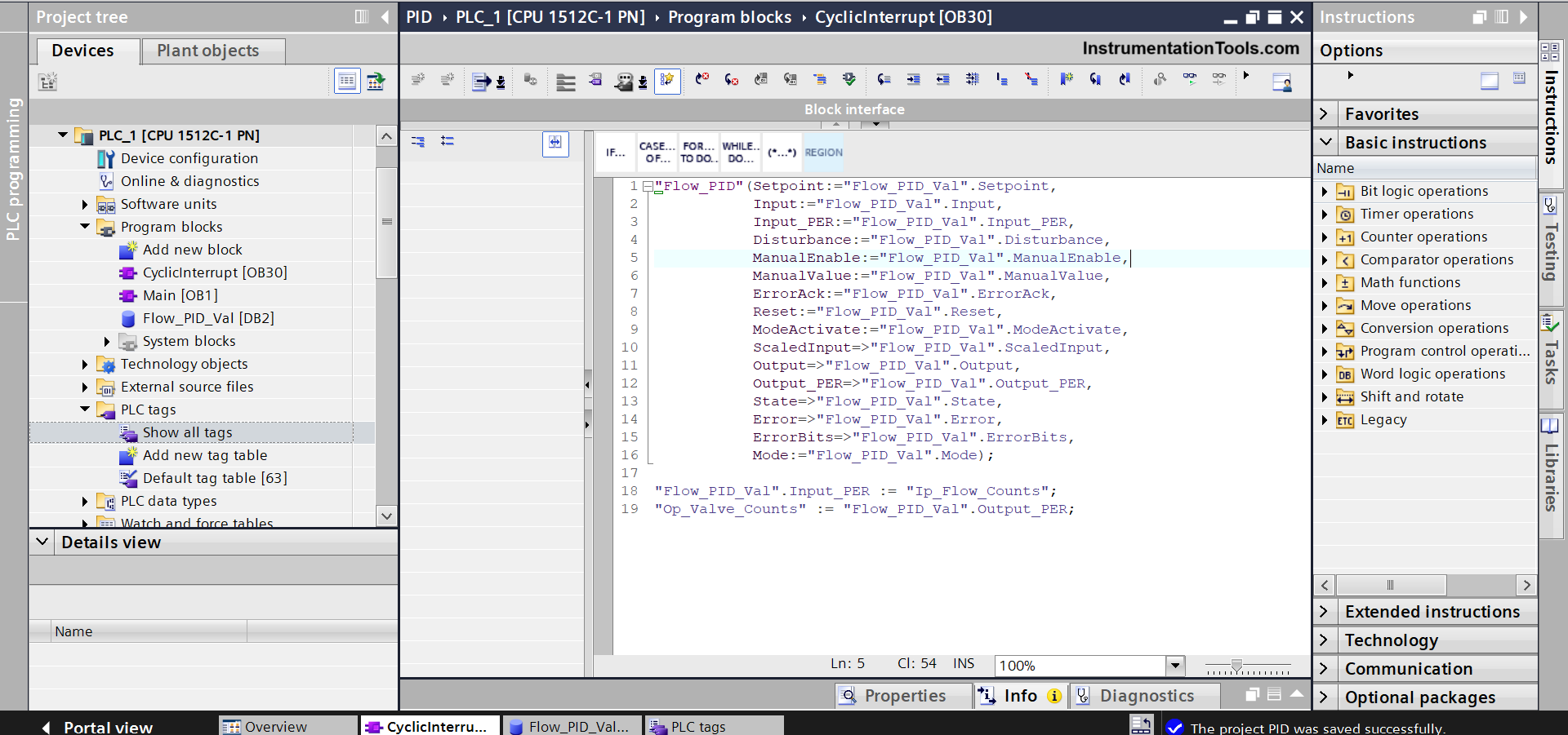
After that, the code will be seen as shown in the below image. Here, you have to define the input and output variables, because as you can see, the by-default names have occurred which are indicated with red underlines.

_In indicates input variables and _Out indicates output variables.

PLC PID control using Structured Text

For simplicity, we will create a DB or data block named Flow_PID_Val in the program.

In this DB, we will name all the parameters with exact names and data types as in the function block for simplicity. Then, we will just map these parameters in the program as shown below.

Also, as seen in the last two lines, we are directly moving PLC analog input raw counts into input_per variable and output_per variable from PID into PLC analog output raw counts.

(The variables input and output in the FB are used when you want to link scaled values done in the PLC program and not raw count values; because per stands for peripherals which is nothing but PLC IO’s).

Now, our program is compiled and free from any errors.

How to write PID logic in Structured Text for PLC

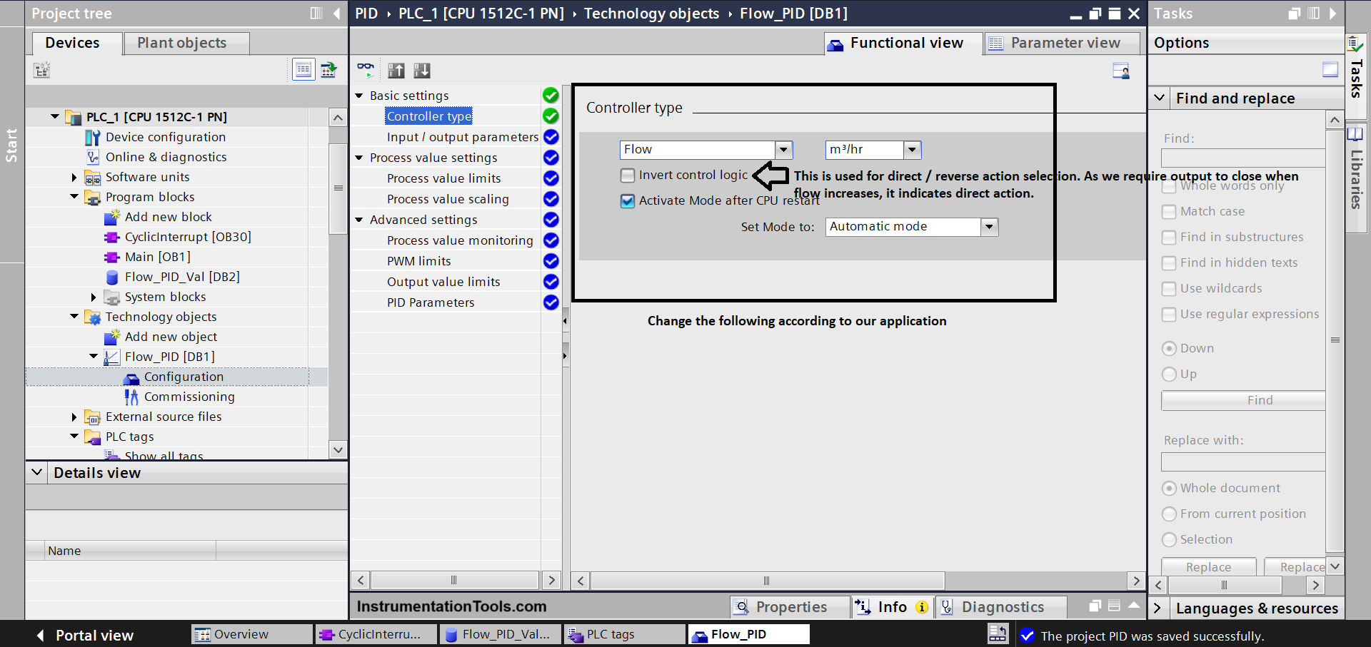
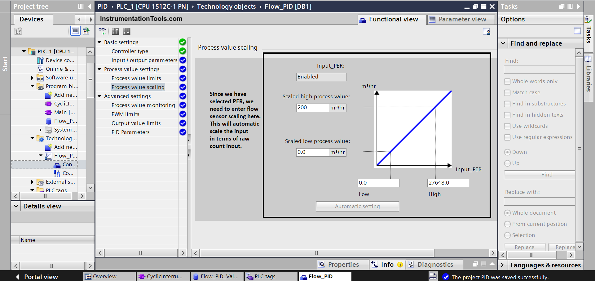
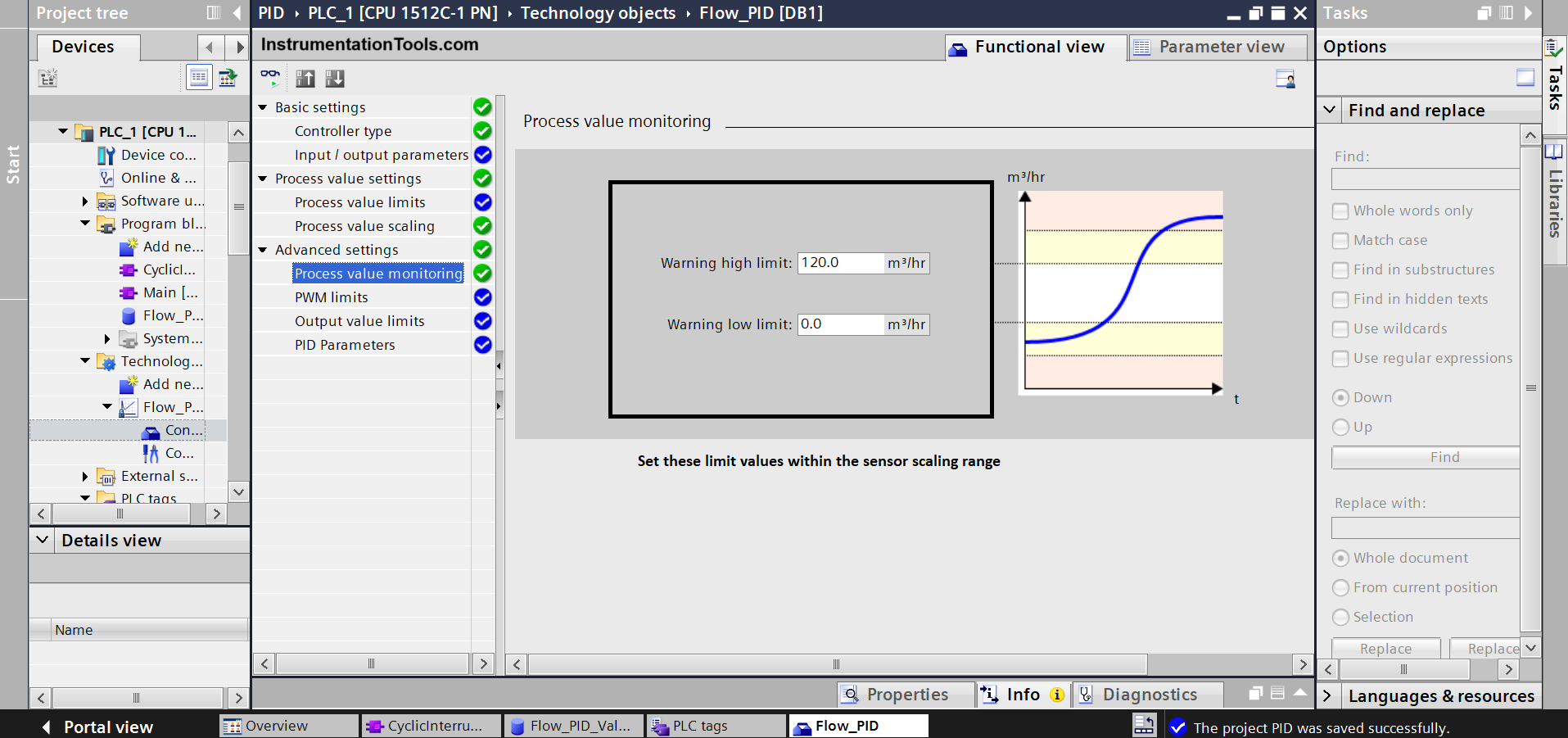
Now, the next important part comes in the configuration and commissioning PID block. Refer to the images one by one below for setting the values (in the configuration window).

Structured Text for PID in PLC systems

Apart from these, no values need to be changed. The output values and PID values will be adjusted automatically.

PLC PID programming tutorial using Structured Text
Structured Text PID control loop in PLC
PLC Structured Text for PID control

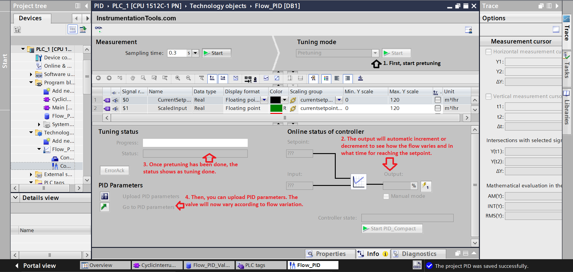
Now, when you have downloaded the program in PLC, you need to go to the commissioning window of the PID tab.

Siemens Tia Portal Commissioning

Refer to the below images for more information. As the raw count of the flow sensor varies, the output counts of the valve will automatically be adjusted to keep it near the setpoint.

PLC PID Structured Text programming techniques

You can refer to the pin description for inputs and outputs of the PID Compact block in the software help file for more information.

In this way, we saw the PLC program for PID using structured text.

Read Next:

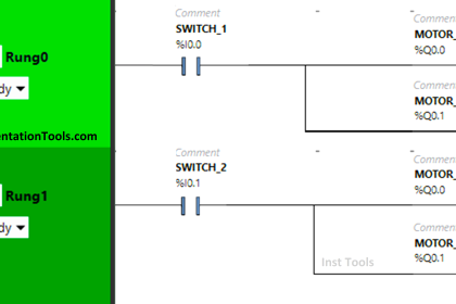
  • Structured Text PLC Logic for Motor Interlock
  • Automatic Curtain Control PLC Programming
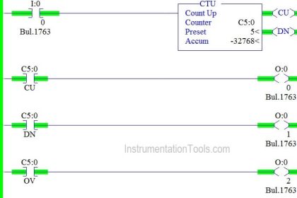
  • Car Wash Program Functional Block Diagram
  • PLC Timer Exercise Coffee Machine Program
  • Configure PID Controller in Schneider PLC
Don't Miss Our Updates
Be the first to get exclusive content straight to your email.
We promise not to spam you. You can unsubscribe at any time.
Invalid email address
You've successfully subscribed !

Continue Reading

PLC Panel and MCC Panel Interface Signals
DCS versus PLC Architecture
PLC Program for Ceramic Burning Oven Conveyor System
What is PCS 7?
Industrial Automation and Control Systems (IACS)
PLC Programming Examples on Industrial Automation
Share This Article
Facebook Whatsapp Whatsapp LinkedIn Copy Link
Share
Leave a Comment

Leave a Reply Cancel reply

Your email address will not be published. Required fields are marked *

Stay Connected

128.3kFollowersLike
69.1kFollowersFollow
210kSubscribersSubscribe
38kFollowersFollow

Categories

Explore More

PLC Handbook
PLC Program using START and STOP Buttons
Types of Failures in Industrial Automation Systems
Difference between Cold Standby and Hot Standby
ICS System Design Considerations
Coil Type Timers in Siemens PLC Programming
PLC Mixing Logic in Liquids on EcoStruxure Machine Expert-Basic
#11 PLC Best Practices – Instrument for Plausibility Checks

Keep Learning

Configuration of Siemens VFD Using TIA Portal

Configuration of Siemens VFD Using TIA Portal Start drive

Instrumentation and Control Project Packages

Instrumentation and Control Project Packages – Detail Engineering

PLC Motor Control Circuit

Motor Trip Logic using PLC Programming

Types of Instructions in PLC Programming

Types of Instructions in PLC Programming

OB10 Time of Day Interrupt

Tia Portal – OB10 Time of Day Interrupt Organization Block

PID parameters

PID in Siemens TIA Portal

Data Handling Instructions in PLC Programming

Data Handling Instructions in PLC Programming

PLC Motor Logic

Interconnection between PLC, MCC, LCP & Pumps – Video

Learn More

Interview Questions on Transformers

Electrical & Instrumentation QC Interview Questions

What is Shielded Twisted Pair Cable

What is Shielded Twisted Pair Cable? – Advantages, Disadvantages

Ladder Logic Vs. Other Programming Languages - PLC Basics

Ladder Logic Vs. Other Programming Languages – PLC Basics

Foundation Fieldbus Segment Topology

Foundation Fieldbus (FF) Segment Topology

optical fiber cable junction box

Underwater Fibre Optic Cable

Power Systems Questions & Answers

Power Systems MCQ Series 21

Robot Anatomy

Robot – Anatomy, Configuration, Reference Frame, Characteristics

Fail Safe Switch Circuit

Basics of Fail-safe Circuits

Menu

  • About
  • Privacy Policy
  • Copyright

Quick Links

  • Learn PLC
  • Helping Hand
  • Part Time Job

YouTube Subscribe

Follow US
All rights reserved. Reproduction in whole or in part without written permission is prohibited.
Welcome Back!

Sign in to your account

Username or Email Address
Password

Lost your password?