Inst ToolsInst ToolsInst Tools
  • Ask
  • Courses
  • Videos
  • Q & A
    • Interview
      • Instrumentation
      • Electronics
      • Electrical
      • Practical Questions
    • MCQ
      • Instrumentation MCQ
      • Electrical MCQ
      • Electronics MCQ
      • Control Systems MCQ
      • Analog Electronics MCQ
      • Digital Electronics MCQ
      • Power Electronics MCQ
      • Microprocessor MCQ
      • Multiple Choice Questions
  • EE
    • Electronics
      • Electronics Q & A
      • Electronic Basics
      • Electronic Devices & Circuits
      • Electronics Animation
      • Digital Electronics
    • Electrical
      • Electrical Basics
      • Electrical Q & A
      • Power Electronics
      • Electrical Machines
      • Electrical Animation
      • Power Systems
      • Switchgear & Protection
      • Transmission & Distribution
  • Measure
    • Control Valves
    • Calibration
    • Temperature
    • Pressure
    • Flow
    • Level
    • Analyzers
    • Switches
    • Vibration
    • Solenoid Valve
  • Control
    • PLC Tutorials
    • Control Systems
    • Safety Instrumented System (SIS)
    • Communication
    • Fire & Gas System
  • More
    • Design
    • Tools
    • Animation
    • Basics
    • Formulas
    • Standards
    • TextBooks
    • Common
    • Software
    • Excel Tools
    • Erection & Commissioning
    • Process Fundamentals
    • Videos
    • Books
Search
All rights reserved. Reproduction in whole or in part without written permission is prohibited.
Reading: What is Optical Modulation? – Methods of Optical Modulation
Share
Notification Show More
Font ResizerAa
Inst ToolsInst Tools
Font ResizerAa
  • Courses
  • PLC Tutorials
  • Control Systems
Search
  • Ask
  • Courses
  • Videos
  • Q & A
    • Interview
    • MCQ
  • EE
    • Electronics
    • Electrical
  • Measure
    • Control Valves
    • Calibration
    • Temperature
    • Pressure
    • Flow
    • Level
    • Analyzers
    • Switches
    • Vibration
    • Solenoid Valve
  • Control
    • PLC Tutorials
    • Control Systems
    • Safety Instrumented System (SIS)
    • Communication
    • Fire & Gas System
  • More
    • Design
    • Tools
    • Animation
    • Basics
    • Formulas
    • Standards
    • TextBooks
    • Common
    • Software
    • Excel Tools
    • Erection & Commissioning
    • Process Fundamentals
    • Videos
    • Books
Follow US
All rights reserved. Reproduction in whole or in part without written permission is prohibited.
Inst Tools > Blog > Common > What is Optical Modulation? – Methods of Optical Modulation

What is Optical Modulation? – Methods of Optical Modulation

Optical modulation is a technique used to amplify the signal strength of the light beam in the optical fiber cables.

Last updated: June 23, 2023 2:37 pm
Viral Nagda
Common
No Comments
Share
7 Min Read
SHARE

Optical fiber is one of the fastest modes of data communication in today’s world. Here, data is transmitted in the form of a light source. That means, the electrical energy is converted into light energy during transmission and back to electrical energy from light energy during reception.

Contents
What is Optical Modulation?Methods of Optical Modulation

As the speed of light is very fast, data is transmitted very quickly in this form. One theory that many aren’t familiar with in optical fiber technology is optical modulation. It is one of the most important techniques used for optical fiber communication. In this post, we will learn the concept of optical modulation.

What is Optical Modulation?

First of all, let us first understand what optical fiber does actually. The refraction index of light emitted by a source is set in such a way that it will travel only inside a cable, and not outside it. Due to this, the light is then turned either on or off continuously, at a very high frequency. Data, when 1 or 0, is converted into a light form in this way.

This data is then interpreted at the receiver end, and thus it can identify the data transmitted through the optical form. The cable used to carry this light is an optical fiber cable. In this way, data is transmitted in optical form through optical fiber cables.
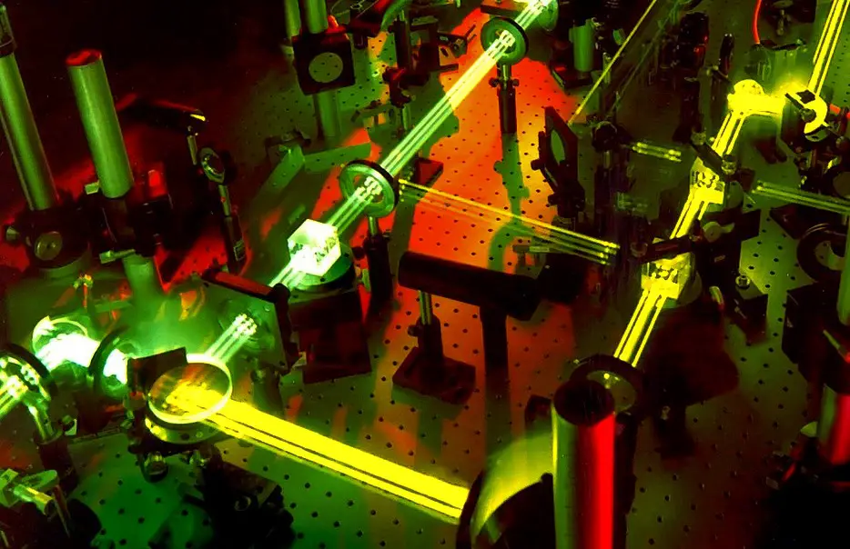
Optical Modulation

Now practically, a laser beam that is used to source light is not always in constant amplitude and frequency. Let alone amplitude or frequency, even the power used in the transmission cannot be constant. There are bound to be some losses in it, due to the electrical nature of cables, noise, and fluctuations. To overcome this issue, a technique is required to manipulate the properties of the light beam. This process is called optical modulation.

As the name suggests, optical modulation is a technique used to amplify the signal strength of the light beam. The data information remains intact as it is, only the electrical and optical strength of the signal is boosted; so that it can travel distances easily and with minimum losses. This is the definition of optical modulation.

Methods of Optical Modulation

There are two general methods of optical modulation. The first one is direct modulation. This is the concept we have already discussed before. Light is a very powerful and fast mode of transmission.

Data transmitted over light beam in 1 or 0 binary format, is direct modulation. This means the natural concept of the optical signal is used to communicate data. There is no need to additionally modulate the data. The signal will travel in optical form and reach the receiver’s end in a quick way.

But, as discussed, it will have its share of losses. Majorly, it occurs due to widening linewidth. At a larger amount of data transfer, this issue widens more. So, direct modulation is used for data less than usually 2.5Gbps.

This loss can also be determined as the signal-to-noise ratio. This ratio must be understood to see how much exactly the data has been lost. This loss can also be called bit error; which means how many bits you transmitted and how many you received.

To overcome this, the second method used is external modulation. As the name suggests, external means are used to modulate the optical signals and boost them in such a way that losses are minimized or even nullified. First, when the normal signal is transmitted, a modulator is used in between which modulates the signal and amplifies it to a great level. It is here in between that data is given, not at the source of the laser beam. This means that data is not traveling from the very first point. This modulator comes immediately at some point after transmission of the laser beam.

The first technique used in external modulation is electro-optical phase modulation. What happens is, first the laser beam is given to a splitter, where the beam is divided into two paths. Then, in one of the paths, electrical binary data is fed. This electric field causes the light speed to slow down by changing its phase. This phase shift and difference is the main reason for amplification. When the beam is then combined after splitting, it can then become either 1 or 0. If the two splits join each other, then the data received is 1; and if the two splits cancel each other, then the data received is 0.

The second technique used in external modulation is the one in which direct light properties are changed to boost them and carry the signal. They can be generally acousto-optic, plasmonic, liquid crystal, micromechanical, or chopper wheels. They directly impact the amplitude, phase, or frequency of light to gain its momentum and carry the signals easily.

If you liked this article, then please subscribe to our YouTube Channel for Electrical, Electronics, Instrumentation, PLC, and SCADA video tutorials.

You can also follow us on Facebook and Twitter to receive daily updates.

Read Next:

  • OLT Working Principle
  • Fiber Optic Measurement
  • Quiz on Optical Fiber Cable
  • Testing of Fiber Optic Cable
  • Use of Isolator in Microwaves
Don't Miss Our Updates
Be the first to get exclusive content straight to your email.
We promise not to spam you. You can unsubscribe at any time.
Invalid email address
You've successfully subscribed !
How Technology is Shaping the Future of Education?
Types of Equipment Needed to Run a Successful Auto Repair Shop
Why is CO2 the Most Promising Refrigerant in Cooling Industry?
Do You Need a VPN on Your Home Computer?
List of 100 Sensors and Transducers Questions
Share This Article
Facebook Whatsapp Whatsapp LinkedIn Copy Link
Share
Leave a Comment

Leave a Reply Cancel reply

Your email address will not be published. Required fields are marked *

Stay Connected

128.3kFollowersLike
69.1kFollowersFollow
208kSubscribersSubscribe
38kFollowersFollow

Categories

Recent Comments

  • Kamli on Top Free PLC Software
  • Guifty Shimica on Top Non-PLC Certification Courses for Automation Professionals
  • Guifty Shimica on Top Non-PLC Certification Courses for Automation Professionals
  • MIHARITSOA Aina Sitraka on Top Non-PLC Certification Courses for Automation Professionals

Related Articles

HVAC Questions & Answers

HVAC Questions & Answers

7 Marketing Strategies for Engineering Companies

7 Marketing Strategies for Engineering Companies

Web Tension Measurement

Web Tension Measurement and Control Technologies

P&ID Legend

What is a Legend? – Piping and Instrumentation Diagram

IP transducer

Pilot Valves and Pneumatic Amplifying Relays

Test Automation in Production Environment

Test Automation in Production Environment – Everything You Should Know

Stainless Steel CNC Machined Parts

Everything You Need to Know About Stainless Steel CNC Machined Parts

Flange Types and Definitions

Flange Types and Definitions

More Articles

Types of Sensors Used in Automobiles

Types of Sensors Used in Automobiles

Digital Output Card With Relay and Wet Contact

Wiring Diagrams of PLC and DCS Systems – DI, DO, AI, AO

Totally Enclosed Fan Cooled (TEFC) Motor

Totally Enclosed Fan Cooled (TEFC) Motors Rampant Winding Burnouts

Top 1000 Analytical Instrumentation Questions & Answers

Top 1000 Analytical Instrumentation Questions & Answers

Innovative Segment Orifice

Pitot-tube Replaced with Innovative Segment Orifice Plate

ANSI Class Relates to PSI

How ANSI Class Relates to PSI ?

Loop Current Step Response (LCSR) Test for RTD

Response Time Test of RTD and Thermocouple

Synchronous Generator Salient Pole vs Non Salient Pole

Follow US
All rights reserved. Reproduction in whole or in part without written permission is prohibited.
Welcome Back!

Sign in to your account

Username or Email Address
Password

Lost your password?