Inst ToolsInst ToolsInst Tools
  • Courses
  • Automation
    • PLC
    • Control System
    • Safety System
    • Communication
    • Fire & Gas System
  • Instrumentation
    • Design
    • Pressure
    • Temperature
    • Flow
    • Level
    • Vibration
    • Analyzer
    • Control Valve
    • Switch
    • Calibration
    • Erection & Commissioning
  • Interview
    • Instrumentation
    • Electrical
    • Electronics
    • Practical
  • Q&A
    • Instrumentation
    • Control System
    • Electrical
    • Electronics
    • Analog Electronics
    • Digital Electronics
    • Power Electronics
    • Microprocessor
  • Request
Search
  • Books
  • Software
  • Projects
  • Process
  • Tools
  • Basics
  • Formula
  • Power Plant
  • Root Cause Analysis
  • Electrical Basics
  • Animation
  • Standards
  • 4-20 mA Course
  • Siemens PLC Course
Reading: Open Loop and Closed Loop Animation
Share
Font ResizerAa
Inst ToolsInst Tools
Font ResizerAa
  • Courses
  • Design
  • PLC
  • Interview
  • Control System
Search
  • Courses
  • Automation
    • PLC
    • Control System
    • Safety System
    • Communication
    • Fire & Gas System
  • Instrumentation
    • Design
    • Pressure
    • Temperature
    • Flow
    • Level
    • Vibration
    • Analyzer
    • Control Valve
    • Switch
    • Calibration
    • Erection & Commissioning
  • Interview
    • Instrumentation
    • Electrical
    • Electronics
    • Practical
  • Q&A
    • Instrumentation
    • Control System
    • Electrical
    • Electronics
    • Analog Electronics
    • Digital Electronics
    • Power Electronics
    • Microprocessor
  • Request
Follow US
All rights reserved. Reproduction in whole or in part without written permission is prohibited.
Inst Tools > Blog > Animation > Open Loop and Closed Loop Animation

Open Loop and Closed Loop Animation

Last updated: July 4, 2016 7:33 am
Editorial Staff
Animation Control Systems
2 Comments
Share
1 Min Read
SHARE

Control Sytem Open Loop and Closed Loop

Open Loop Control System

A control system in which the control action is totally independent of output of the system then it is called open loop control system. Manual control system is also an open loop control systemopen vs closed loop

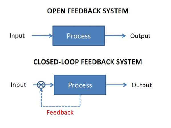
Closed Loop Control System

Control system in which the output has an effect on the input quantity in such a manner that the input quantity will adjust itself based on the output generated is called closed loop control system. Open loop control system can be converted in to closed loop control system by providing a feedback. This feedback automatically makes the suitable changes in the output due to external disturbance. In this way closed loop control system is called automatic control system. Figure below shows the block diagram of closed loop control system in which feedback is taken from output and fed in to input.

Open Loop system vs Closed Loop System

Also Read: Basics of Alarms & Trips in Control Systems

Don't Miss Our Updates
Be the first to get exclusive content straight to your email.
We promise not to spam you. You can unsubscribe at any time.
Invalid email address
You've successfully subscribed !

Continue Reading

The need for automatic controls
Process Interlocks and Trips
Motor Control Signal Interface
Instrumentation Engineer Activities & Documents – Detail Design Phase
Encoder Working Principle
Magnetic Float Level Switch Working Animation
Share This Article
Facebook Whatsapp Whatsapp LinkedIn Copy Link
Share
2 Comments
  • Arvin Mistry says:
    June 26, 2023 at 8:08 pm

    This site has many good articles for study in various control systems and Electronic Components.

    Reply
  • Sanjeev Deshpande says:
    January 3, 2024 at 11:36 am

    Animations and examples are quite realistic for the students to understand. Very appreciable presentation

    Reply

Leave a Reply Cancel reply

Your email address will not be published. Required fields are marked *

Stay Connected

128.3kFollowersLike
69.1kFollowersFollow
210kSubscribersSubscribe
38kFollowersFollow

Categories

Explore More

Difference Between Single Pair Ethernet and Traditional Ethernet
Why 24 Volts DC Power Supply is used? – Industrial Automation Systems
How-to do Security of SCADA Systems?
Comparison of Proportional Integral Derivative Controllers (PID)
What is ON/OFF Valve ?
Basics of Motion Controllers
Understanding the Scan Cycle of SIEMENS PLC
Pitot Tube Working Principle

Keep Learning

Difference Between SCADA and HMI

Difference Between SCADA and HMI

Sinking and Sourcing Devices Operation

PLC Sinking and Sourcing Explanation

Node-RED in PLC Automation

Node-RED in PLC Industrial Automation

Process Control System

Basics of Process Control Systems

Control Room Design Guidelines

Control Room Design Guidelines

2-wire loop-powered transmitter

Loop Controller HART Signal Noise

gate-valve-principle-animation

Basics of Gate Valves

Single Loop Control

Cascade Control Principle

Learn More

LIC and FIC Controllers

What LIC and FIC Controllers will do?

Permit to Work System Online Test

Permit to Work System Online Test

PLC Stop - Start Circuit

Introduction to PLC Ladder Diagrams

Steam conditioning valves

Concept of Steam Conditioning Valves

Vibration Probe Field Setting Procedure

How to do calibration checks of vibration Probe, extension cable and vibration monitor

What is Hydraulics

What is Hydraulics?

Power Systems Questions & Answers

Power Systems MCQ Series 21

Oval gear Flow Meter Principle

Oval Gear Meter – Principle, Advantages, Limitations, Applications

Menu

  • About
  • Privacy Policy
  • Copyright

Quick Links

  • Learn PLC
  • Helping Hand
  • Part Time Job

YouTube Subscribe

Follow US
All rights reserved. Reproduction in whole or in part without written permission is prohibited.
Welcome Back!

Sign in to your account

Username or Email Address
Password

Lost your password?