Open Vessel Level Calculation
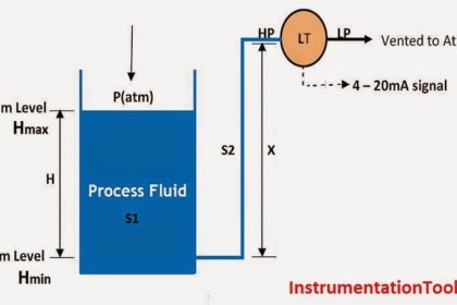
Open tank : Level Transmitter installed at HP Tapping Point

In above example, transmitter installed exactly at HP tapping point i.e. at 0 % Level
Calibration Range
LRV or 4mA point = 1.1 * 0 = 0 inH2O
URV or 20mA Point = Head = 1.1*50” = 55 inH2O
Cal. Range = 0 to 55 inH2O
Open Tank : Level Transmitter Zero Scale above HP Tapping Point

In above example, transmitter installed point and Tank Zero Percentage level are different.
Calibration Range
LRV or 4mA point = Head1 = 1.1*10” = 11 inH2O
URV or 20mA Point = Head2 = 1.1*50” = 55 inH2O
Cal. Range = 11 to 55 inH2O
Open Tank : Level Transmitter Installed below HP Tapping Point

Calibration Range
LRV or 4mA point = Head1 = 1.1*10” = 11 inH2O
URV or 20mA Point = Head1 + Head2 = (1.1*10”) + (1.1*50”) = 66 inH2O
Cal. Range = 11 to 66 inH2O
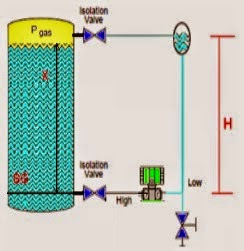
Closed Tank Level Calculation (Wet Leg)
Closed Tank : Level Transmitter installed at HP Tapping Point

In above example, transmitter installed exactly at HP tapping point i.e. at 0 % Level
Calibration Range
LRV or 4mA point = Phigh – Plow = 0 – Head1 = 0 – (1.2*70”) = -84”H2O
URV or 20mA Point = Phigh – Plow = Head2 – Head1 = (1.1*50”)] – (1.2*70”) = -29”H2O
Cal. Range = -84 to -29 inH2O
Closed Tank : Level Transmitter Zero Scale above HP Tapping Point

In above example, transmitter installed point and Tank Zero Percentage level are different.
Calibration Range
LRV or 4mA point = Phigh – Plow = Head2 – Head1 = (1.1*10”) – (1.2*70”) = -73”H2O
URV or 20mA Point = Phigh – Plow = (Head2 + Head3) – Head1
= [(1.1*10”) + (1.1*40”)] – (1.2*70”) = -29”H2O
Cal. Range = -73 to -29 inH2O
Closed Tank : Level Transmitter Installed below HP Tapping Point

Calibration Range
LRV or 4mA point = Phigh – Plow = Head2 – Head1 = (1.1*10”) – (1.2*80”) = -85”H2O
URV or 20mA Point = Phigh – Plow = (Head2 + Head3) – Head1
= [(1.1*10”) + (1.1*50”)] – (1.2*80”) = -30”H2O
Cal. Range = -85 to -30 inH2O


Easy Calculations & in Understandable way. Thanks Bharadwaj sir.
Sir how to mount dot in for vaccum tank level measurement already we are using magnetic level gauge which works on magnetostrictive principle.
Thank you this a simple calculation
It’s really use full & simple calculations sir.Thank you very much sir.
I am so happy finding this learning web site. Suggested to my friends as well. Using daily to improve my skills. Thanks for this web site creator.
We have two articles one about zero elevation suppression and one about URV and LRV calibration range. M question is in calibration range we need to include the pressure head in HP tapping or remove? same for suppression.
How to calibrate LT close tank under vacuum.