This article is about Controlling Motor in Forward and Reverse direction by using Limit Switches and Push Buttons.
Generally, this connection is mainly used on conveyor systems in industries. Whenever the start button is pressed the motor will start rotating either Forward or Reverse depending on the input, after the signal from Limit switches were received motor stops rotating.
The main notify point in this connection is the interlock system i.e., When the motor is rotating in Forward direction then you cannot make the motor rotate in a Reverse direction unless you Stop the motor before changing its direction and vice versa.
Components
The below shows the required components for the motor forward & reverse circuits.
- Miniature Circuit Breaker (MCB)
- Contactor
- Limit Switches
- Push Buttons
- Start Push Button
- Stop Push Button
- Multimeter
- Clamp meter
Circuit Diagrams
This Forward and Reverse control has two circuits.
They are:
- Power Circuit
- Control Circuit
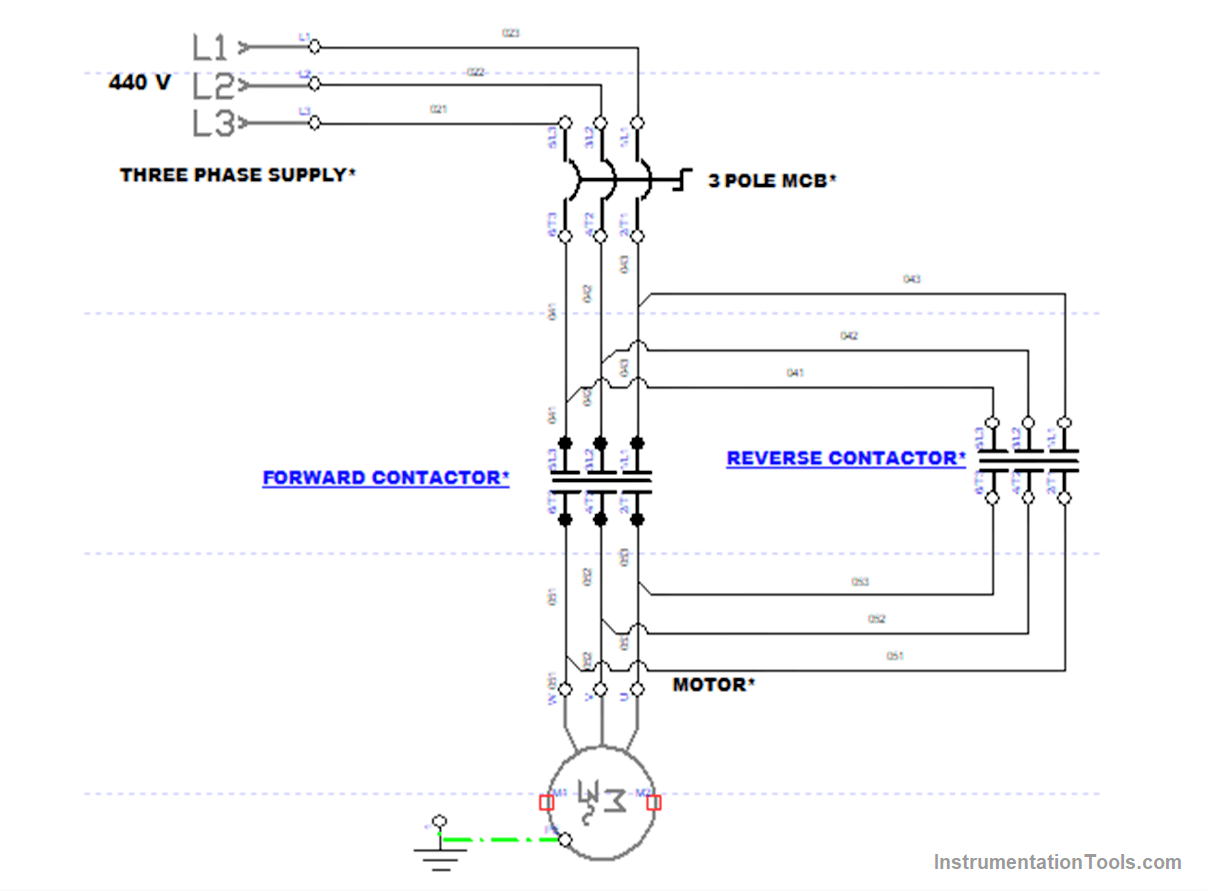
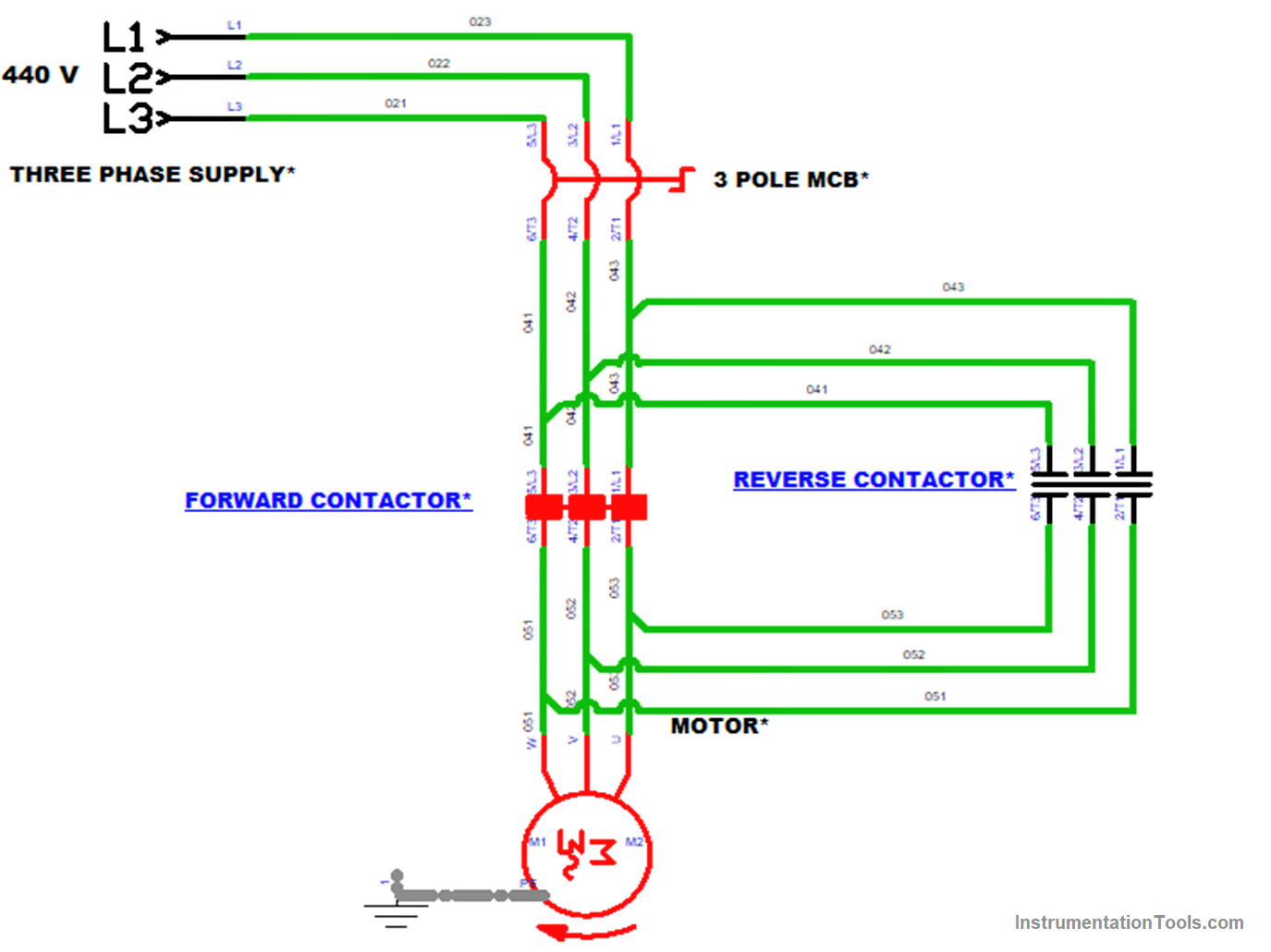
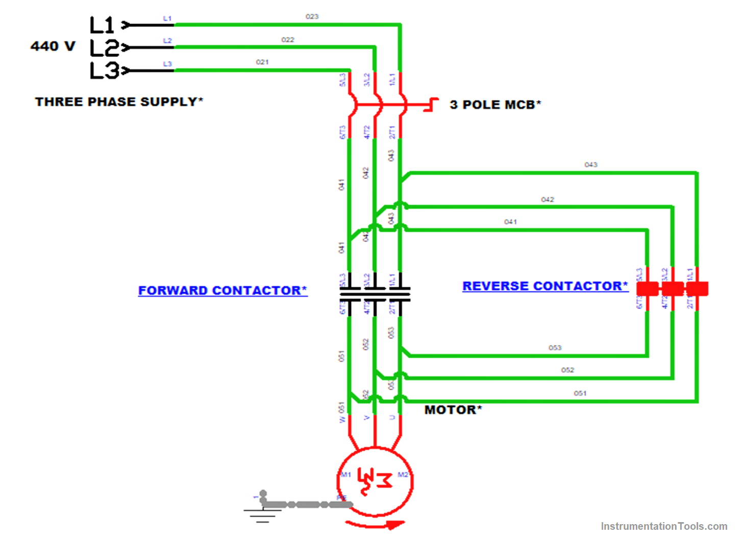
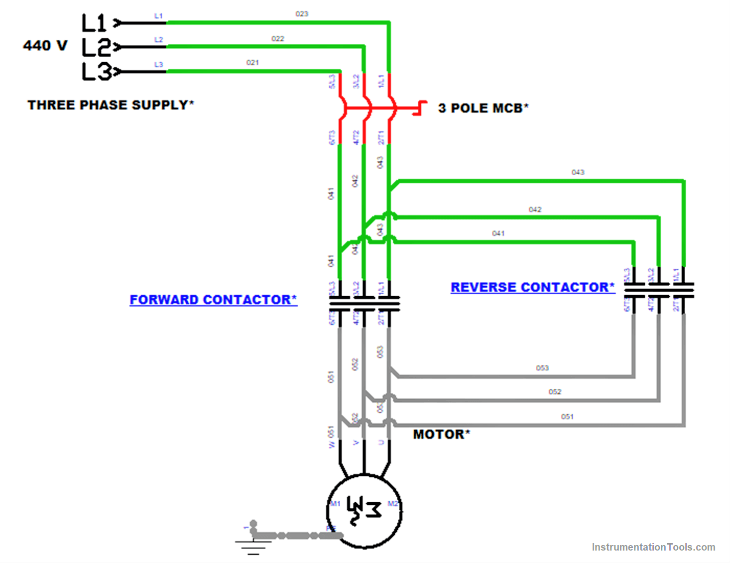
Power Circuit
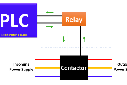
The main components used in the power circuit are 3 Pole MCB and two contactors for forward & Reverse control of the motor.
MCB protects the motor from overload and uneven fluctuations. Contactors are used to make and break the contact to the load (motor).
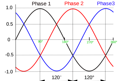
An important note in this connection is any of the two phases were interchanged for the opposite directions of rotation in the motor.
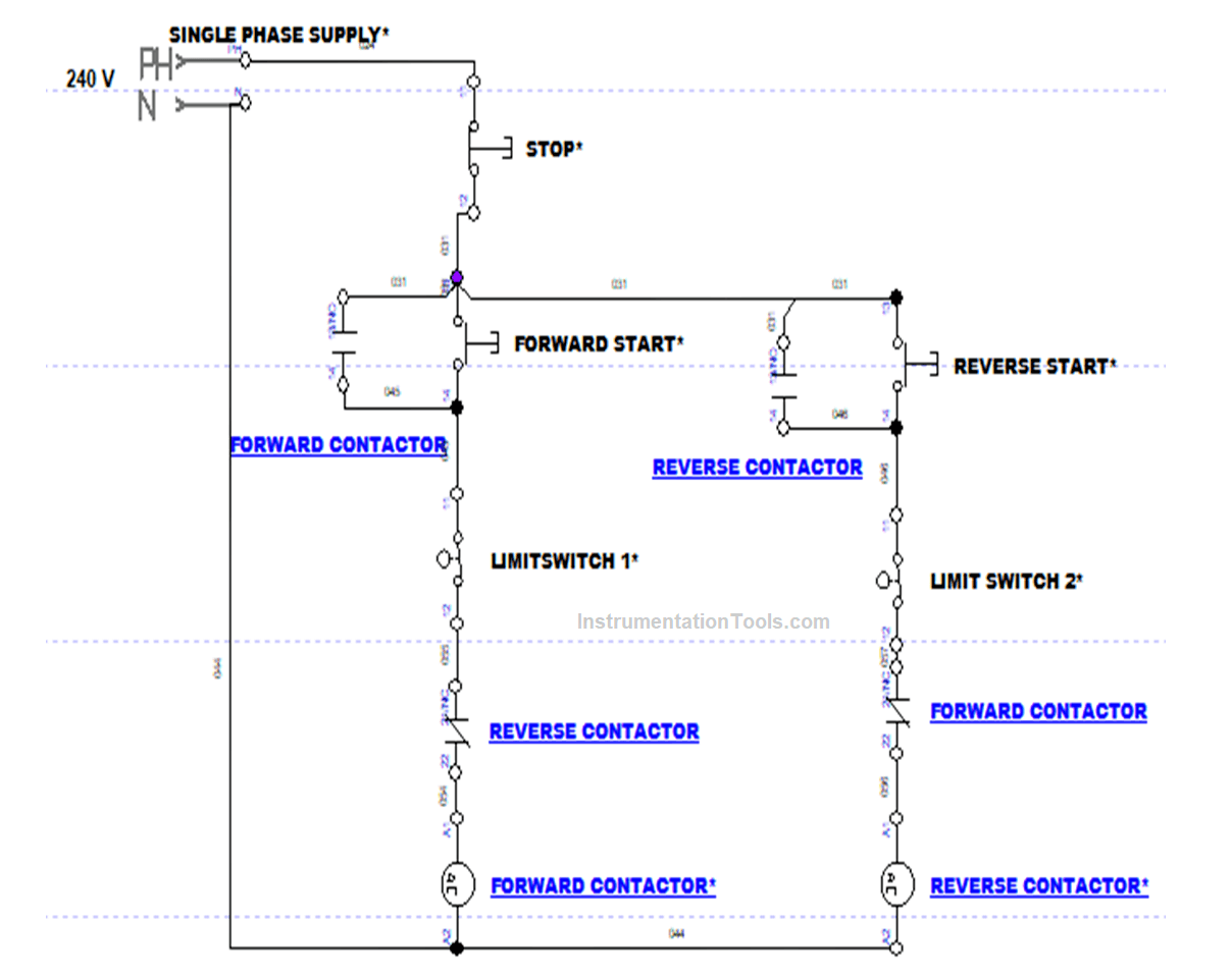
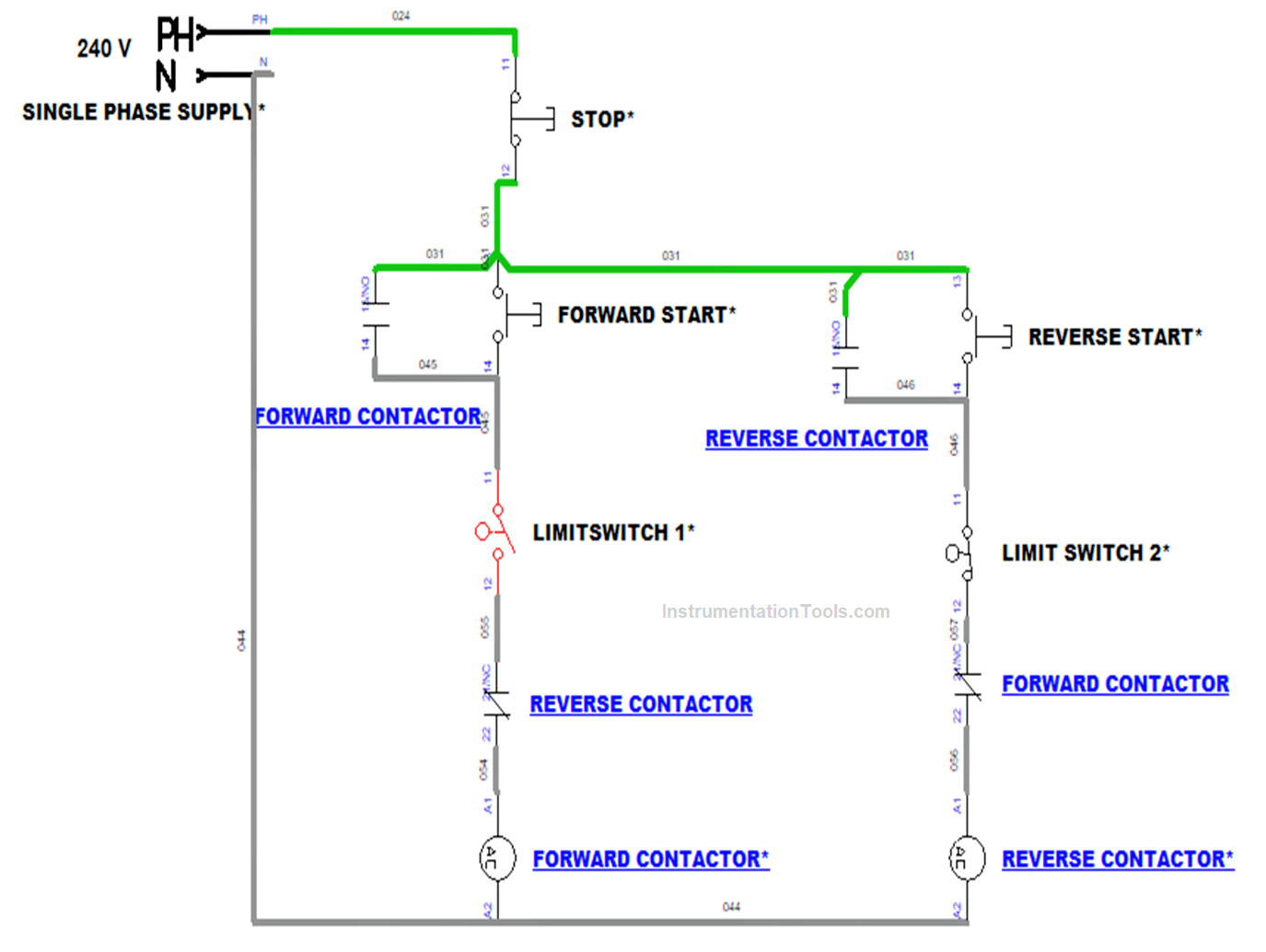
Control Circuit
The motor in the Power circuit is controlled by components in the control circuit.
The main components in the control circuit were Start & Stop Pushbutton, Contactor coils, and Limit switches.
Limit switches were used to sense the end position & Contactor coils were used for energizing the contactor in the power circuit.
Motor Forward and Reverse Direction Control Operation
Three-phase supply of 440V is given to the power circuit for controlling the motor. The given supply passes through 3 pole MCB.
MCB, the electromechanical device actuated manually for giving the supply to the contactor and Load.
For the control circuit, a voltage of 240 V was given for controlling the load through Contactor. Then Forward Start button is pressed.
The control supply goes to the NC (Normal Close) contacts of Limit Switch 1 and Reverse Contactor, which makes the forward contactor to energize.
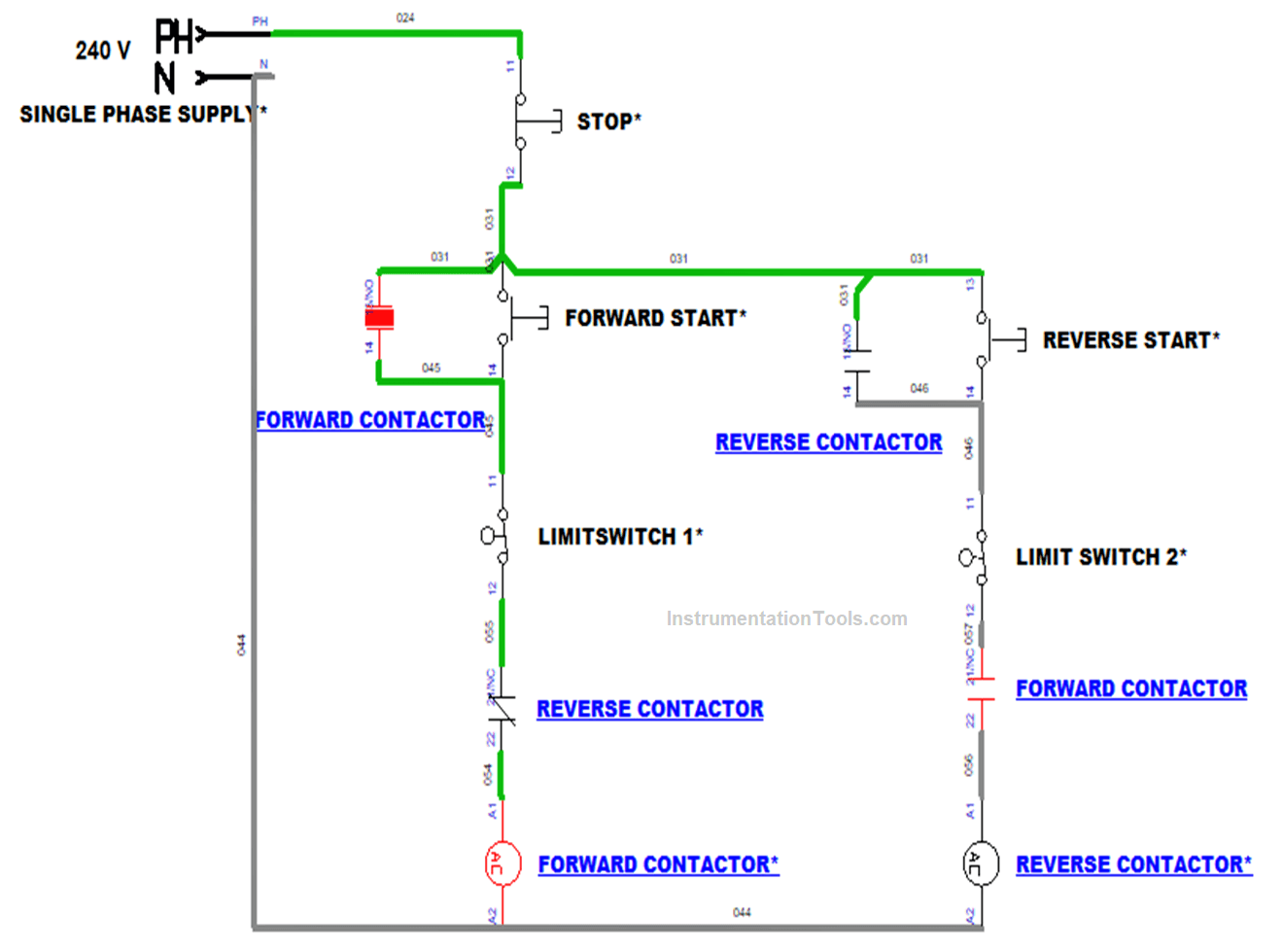
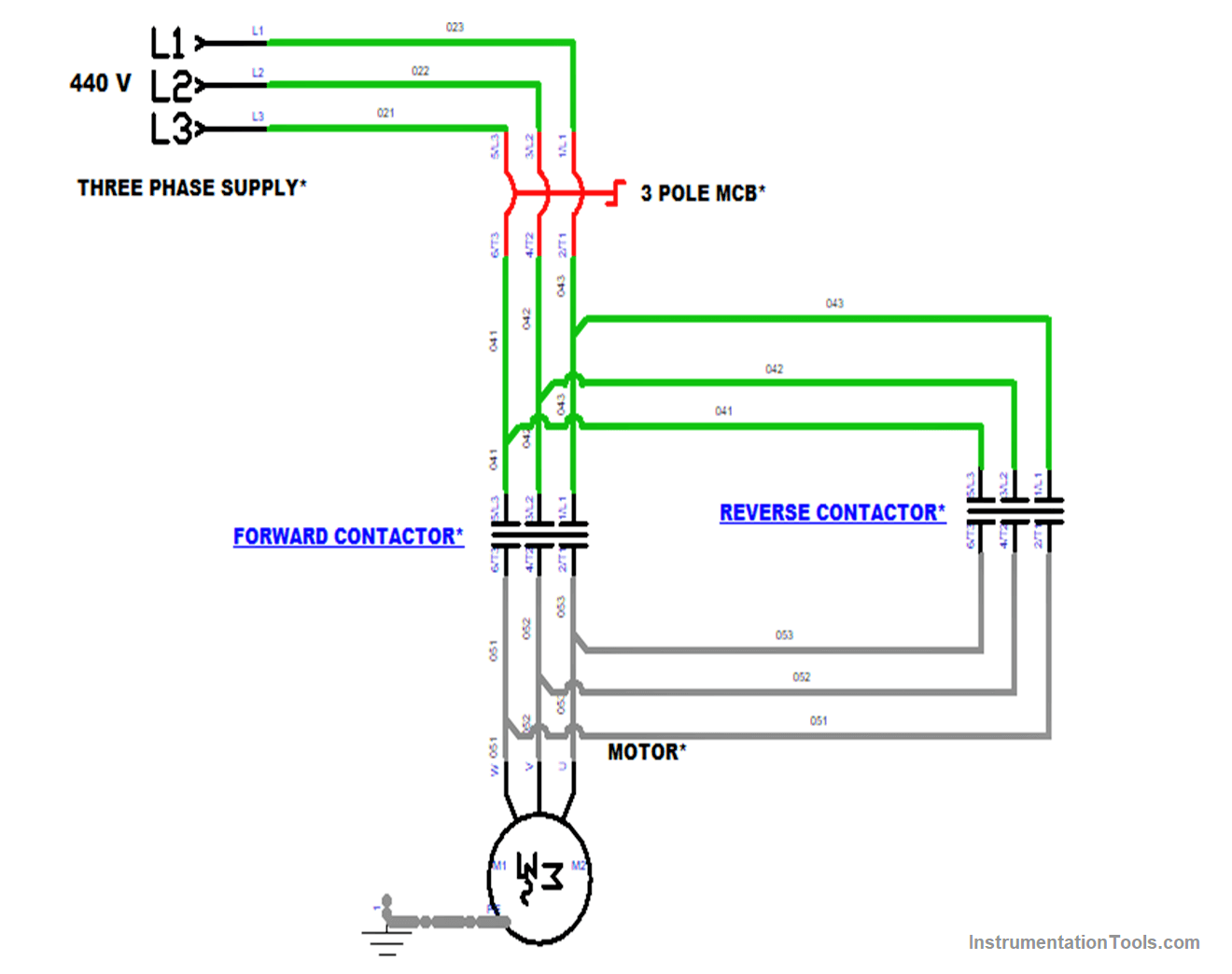
By the energization of the Forward contactor coil in the control circuit, the Forward contactor in the power circuit got actuated which makes the motor run in a forward (clockwise) direction.
As soon as the Limit Switch 1 got the signal, it states changes from NC (Normally Close) to NO (Normally Open) which will de-energize the Forward Contactor coil.
The forward Contactor coil in the control circuit was de-energized in the control circuit so the Forward contactor was deactivated.
So the power to the motor was disconnected. Now motor was stopped rotating.
Since Forward and Reverse control was used mostly in conveyors after reaching the limit it should be reversed.
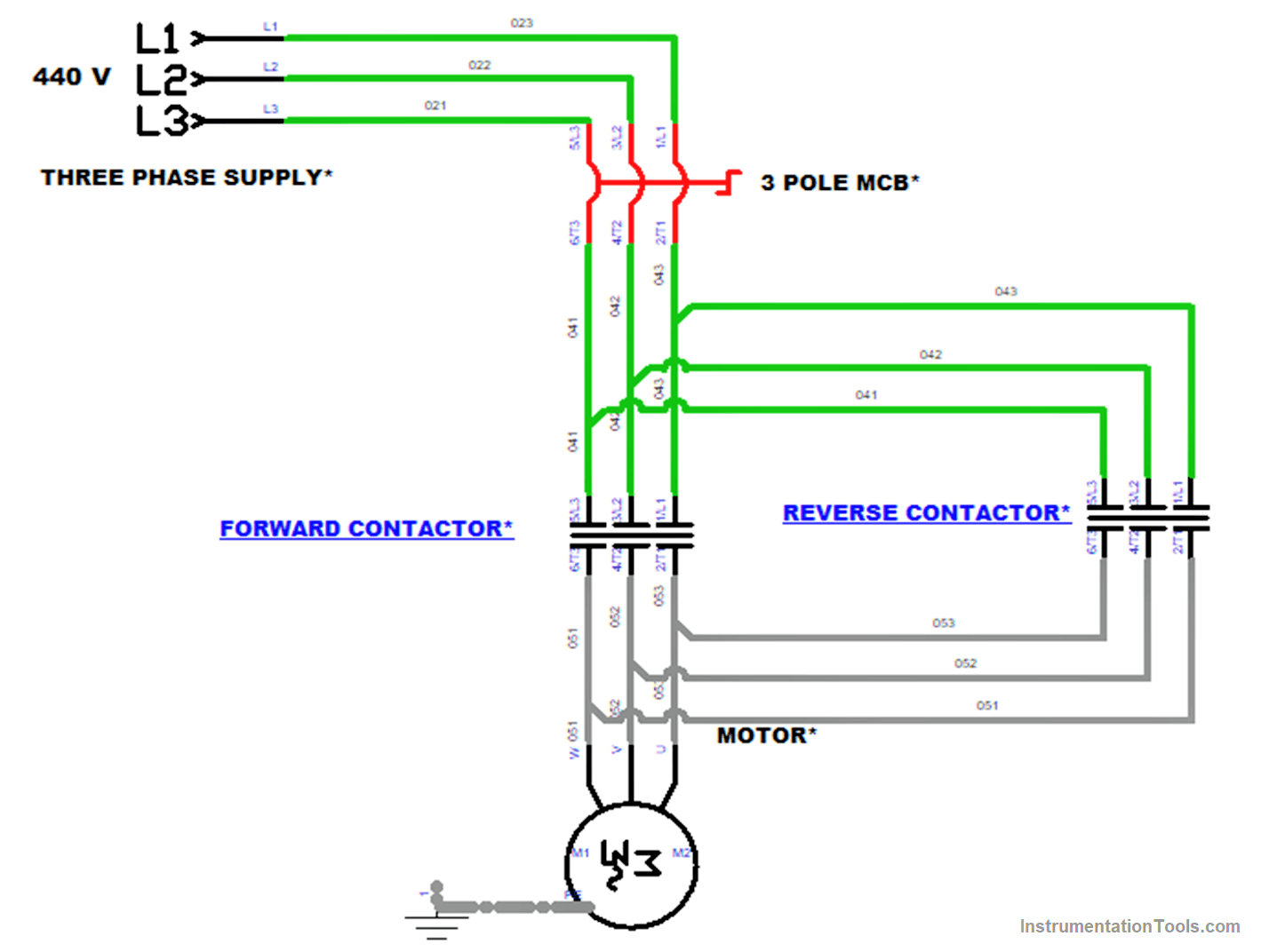
So, for Reverse control the Reverse Start button is pressed for that Reverse Contactor gets energized.
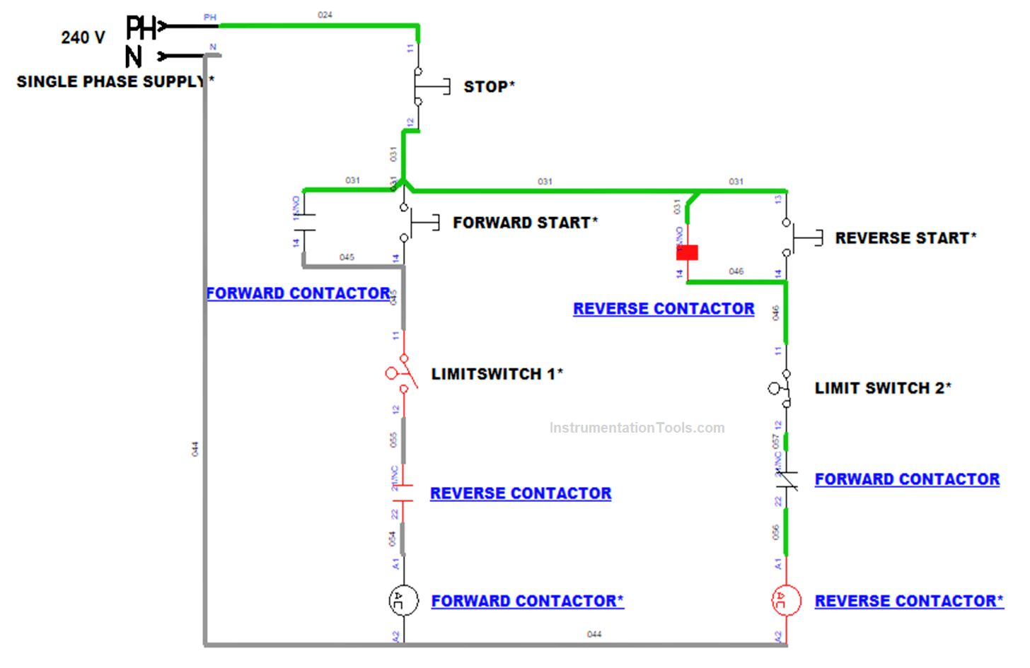
Here, the Reverse contactor coil gets energized in the control circuit which makes the Reverse contactor actuate in the power circuit.
By the Reverse contactor, the power was supplied to the motor, now the motor starts to rotate in a reverse (Anti-clockwise) direction
In this reverse control also after getting the signal from Limit Switch 2, the Reverse contactor gets de-energized.

So, the de-energize of the reverse contactor coil in the control circuit makes the reverse contactor deactivate in the power circuit.
So the power to the motor was stopped and the motor stops rotating.
Thus, the process continues. After reaching the Limit Forward Start is pressed and Motor starts rotating in Forward direction. This loop continues until the stop button is pressed.
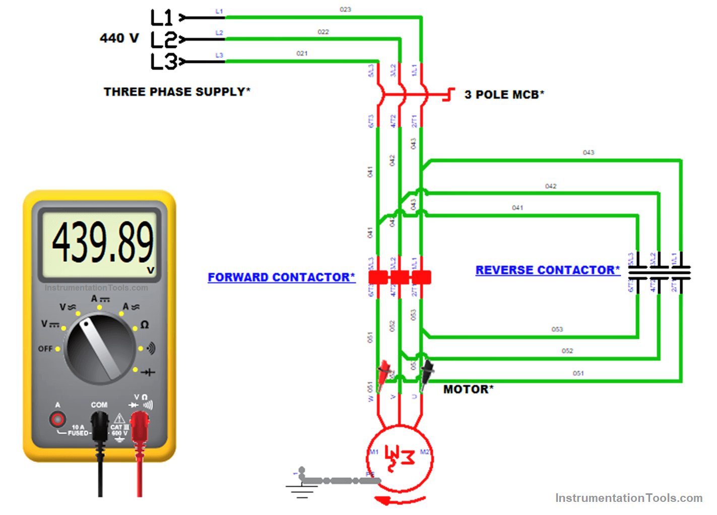
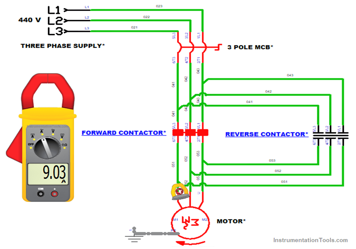
Voltage and Current are measured using Multimeter and Clamp meters respectively. Voltage and Current will be the same in both Forward and Reverse directions.
For measuring voltage, the two probes of the Multi-meter were placed in any of the two lines in the circuit. It may be L1, L2 or L2, L3 or L1, L3.
The voltage value is measured and displayed in the display. It is a Three Phase supply so the obtained voltage value is ~ 440 V
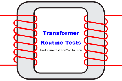
Current is measured using a Clamp meter. A clamp meter is also known as Split Core Transformers, the iron core of the transformer is hinged as in the case of pliers.
With the split-core current transformer and the attached Ampere meter, one can measure alternating currents without interrupting the circuit.
For measuring current, a plier in the meter is placed in any one of the conductors. L1 or L2 or L3. The measured value is displayed in the display.
Applications
- For transferring materials in conveyor
- Automatic Gate Open and Close
- Lifting materials in Hoist control
If you liked this article, then please subscribe to our YouTube Channel for Instrumentation, Electrical, PLC, and SCADA video tutorials.
You can also follow us on Facebook and Twitter to receive daily updates.
Read Next: