This article discusses a raw material mixing system controlled using Siemens TIA Portal software. The system is designed to mix four types of raw materials in a tank using two dosing methods: weight-based and time-based. During the mixing process, the raw materials undergo heating and cooling for a specific duration. The PLC system is equipped with an alarm indicator that activates after all process stages have been completed.
Program Objective

Steps of the Raw Material Processing Procedure
System Initialization: The system starts operating by mixing four raw materials in a predetermined order.
Material Filling Stage:
a) Material A is added to the tank with a weight of 8 kg.
b) Material B is added to the tank with a weight of 12 kg.
c) The mixer is activated to ensure proper blending of the materials.
d) Material C is introduced by opening the valve for 2 seconds.
e) The heater is turned ON and operates for 12 seconds to heat the mixture.
f) Material D is introduced by opening the valve for 12 seconds.
Cooling Stage: The cooling fan is activated and operates for 12 seconds to lower the mixture’s temperature.
Process Completion:
- The mixer is turned off after the mixing process is complete.
- The alarm indicator lights up, indicating that the entire process has been completed.
System Reset:
- The system can only be restarted if the tank is empty.
- Tank emptying via the outlet valve can only be done manually.
Mapping Details
| S.No. | Comment | Input (I) | Output (Q) | Memory Bit | Memory Word | Timers |
|---|---|---|---|---|---|---|
| 1 | START | I0.0 | ||||
| 2 | STOP | I0.1 | ||||
| 3 | PB_ALARM_STOP | I0.2 | ||||
| 4 | PB_VALVE_OUT | I0.3 | ||||
| 5 | VALVE_A | Q0.0 | ||||
| 6 | VALVE_B | Q0.1 | ||||
| 7 | AGITATOR_MIXER | Q0.4 | ||||
| 8 | VALVE_C | Q0.2 | ||||
| 9 | HEATER | Q0.5 | ||||
| 10 | VALVE_D | Q0.3 | ||||
| 11 | FAN | Q0.6` | ||||
| 12 | ALARM | Q0.7 | ||||
| 13 | VALVE_OUT | Q1.0 | ||||
| 14 | WHIEGING INDICATOR | MW2 | ||||
| 15 | TIMER_VALVE_C | DB1 | ||||
| 16 | TIMER_HEATER | DB2 | ||||
| 17 | TIMER_VALVE_D | DB3 | ||||
| 18 | TIMER_FAN | DB4 | ||||
| 19 | SYSTEM_ON | M0.0 | ||||
| 20 | IR_TIMER_VALVE_C | M0.1 | ||||
| 21 | IR_TIMER_HEATER | M0.2 | ||||
| 22 | IR_TIMER_VALVE_D | M0.3 | ||||
| 23 | IR_TIMER_FAN | M0.4 | ||||
| 24 | TEMP_TIMER_VALVE_C | M0.5 | ||||
| 25 | TEMP_TIMER_HEATER | M0.6 | ||||
| 26 | TEMP_TIMER_VALVE_D | M0.7 | ||||
| 27 | TEMP_TIMER_FAN | M1.0 |
Mixing and Dosing PLC Logic
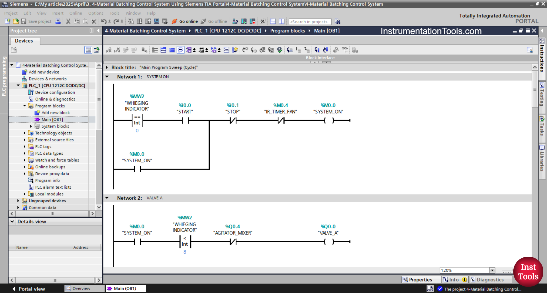
NETWORK 1 (SYSTEM ON)
In this Network, the memory bit SYSTEM_ON (M0.0) will be in a HIGH state if the value in the memory word WEIGHING INDICATOR (MW2) is Equal to “0” and the START(I0.0) button is pressed. The S memory bit SYSTEM_ON (M0.0) will remain in a HIGH state even though the PB_START (I0.0) button has been released, because it uses Latching.
If the STOP (I0.1) button is pressed or the NC contact of the memory bit IR_TIMER_ FAN (M0.4) is in a HIGH state, then the memory bit SYSTEM_ON (M0.0) will return to a LOW state.
NETWORK 2 (VALVE A)
In this Network, the output of VALVE_A (Q0.0) will be OPEN when the NO contact of the memory bit SYSTEM_ON (M0.0) is in HIGH state and the value of the memory word WEIGHING INDICATOR (MW2) is Less Than “8”.
The output of VALVE_A (Q0.0) will be CLOSED when the NC contact of AGITATOR_MIXER (Q0.4) is in HIGH state.
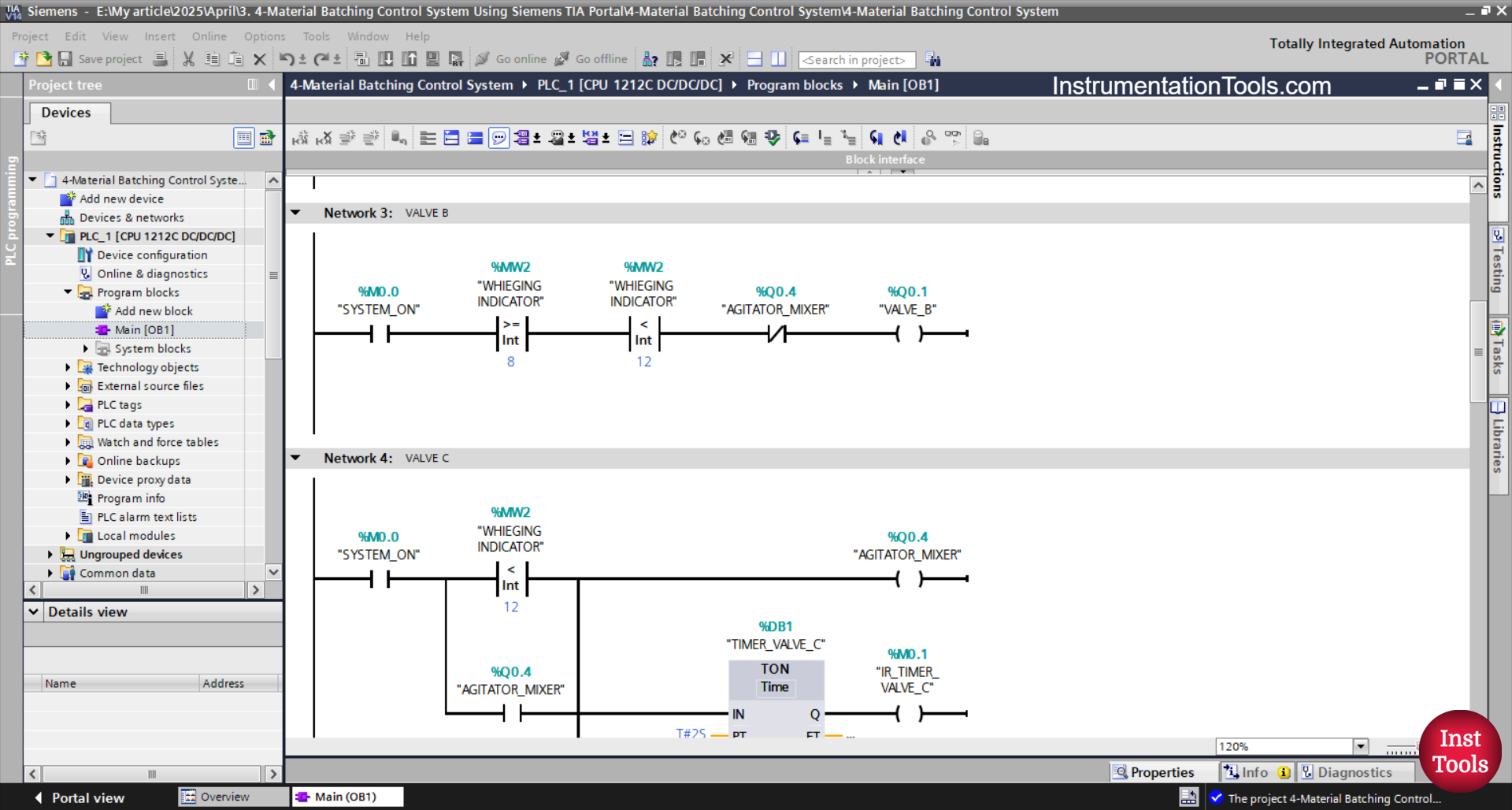
NETWORK 3 (VALVE B)
The output of VALVE_B (Q0.1) will be OPEN when the NO contact of the memory bit SYSTEM_ON (M0.0) is in HIGH state and the value of the memory word WEIGHING INDICATOR (MW2) is Greater than or Equal to “8” and Less than “12”.
If the NC contact of AGITATOR_MIXER (Q0.4) is in HIGH state, then the output of VALVE_B (Q0.1) will be CLOSED.
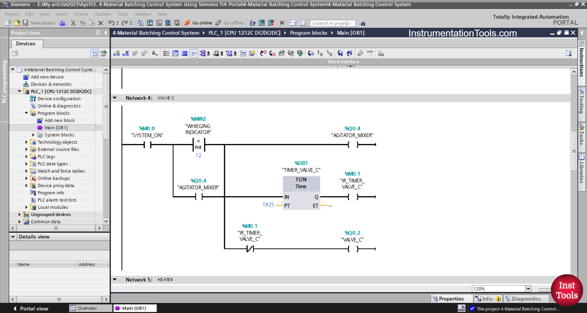
NETWORK 4 (VALVE C)
The AGITATOR_MIXER (Q0.4) output will be ON and the VALVE_C (Q0.2) output will be OPEN when the NO contact of the memory bit SYSTEM_ON (M0.0) is in HIGH state and the value of the memory word WEIGHING INDICATOR (MW2) is Equal to “12”.
The TIMER_VALVE_C (DB1) timer will start counting for 2 seconds.
After finishing counting, the VALVE_C (Q0.2) output will be CLOSED because of the Interlock of the memory bit IR_TIMER_VALVE_C (M0.1).

NETWORK 5 (HEATER)
The HEATER (Q0.5) output will be ON when the NO contact of the memory bits SYSTEM_ON (M0.0) and IR_TIMER_VALVE_C (M0.1) are in the HIGH state. Although the NO contact of the memory bit IR_TIMER_VALVE_C (M0.1) is in the LOW state, the HEATER (Q0.5) output will remain ON because it uses Latching.
The TIMER_HEATER (DB2) timer will start counting for 12 seconds.
After finishing counting, the HEATER (Q0.5) output will be OFF because of the Interlock of the memory bit IR_TIMER_HEATER (M0.2).
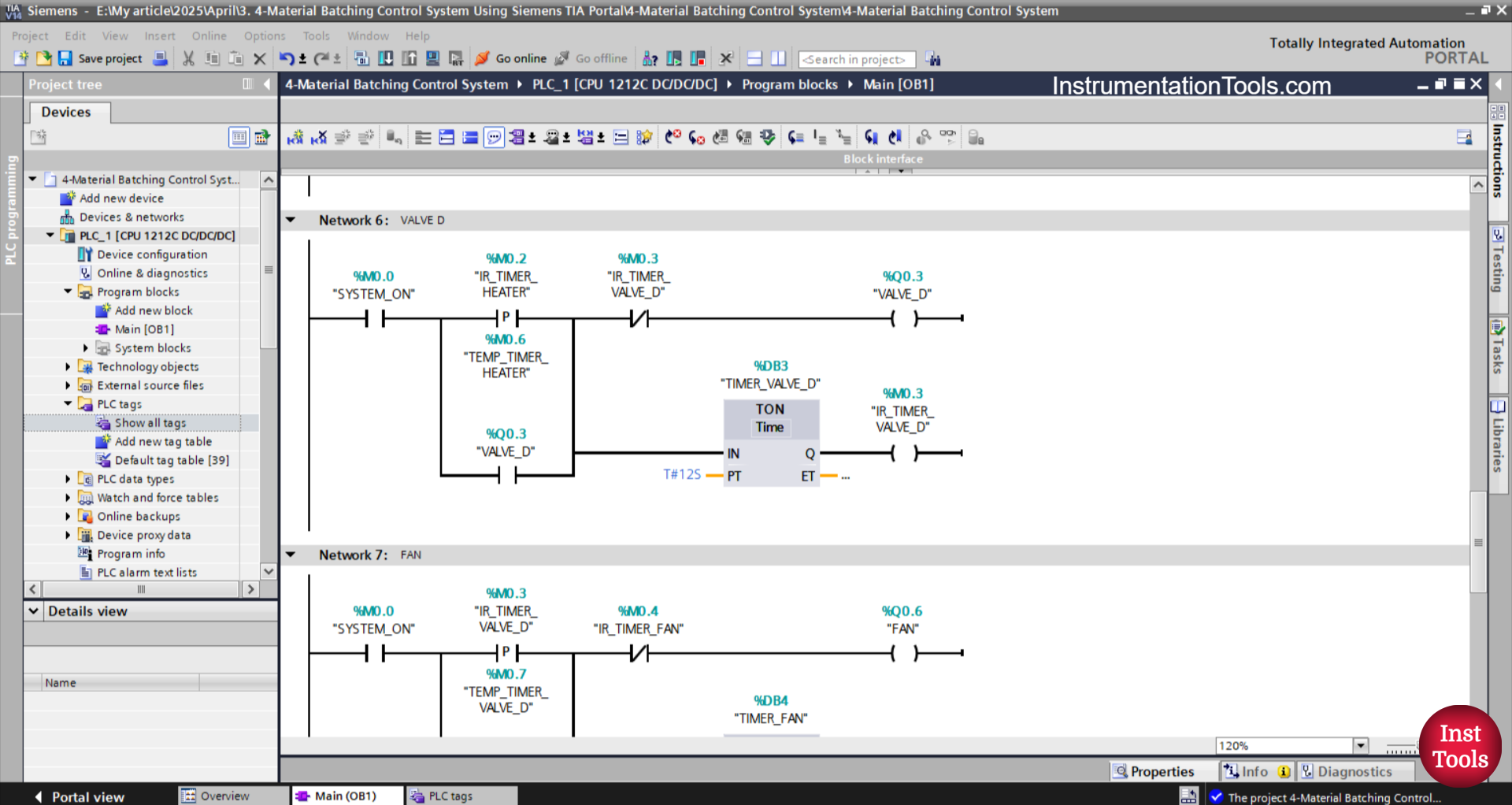
NETWORK 6 (VALVE D)
The output of VALVE_D (Q0.3) will be OPEN when the NO contact of the memory bits SYSTEM_ON (M0.0) and IR_TIMER_HEATER (M0.2) are in the HIGH state. Although the NO contact of the memory bit IR_TIMER_HEATER (M0.2) is in the LOW state, the output of VALVE_D (Q0.3) will remain OPEN because it uses Latching.
The TIMER_ VALVE_D (DB3) timer will start counting for 12 seconds.
After finishing counting, the output of VALVE_D (Q0.3) will be CLOSE because of the Interlock of the memory bit IR_TIMER_ VALVE_D (M0.3).
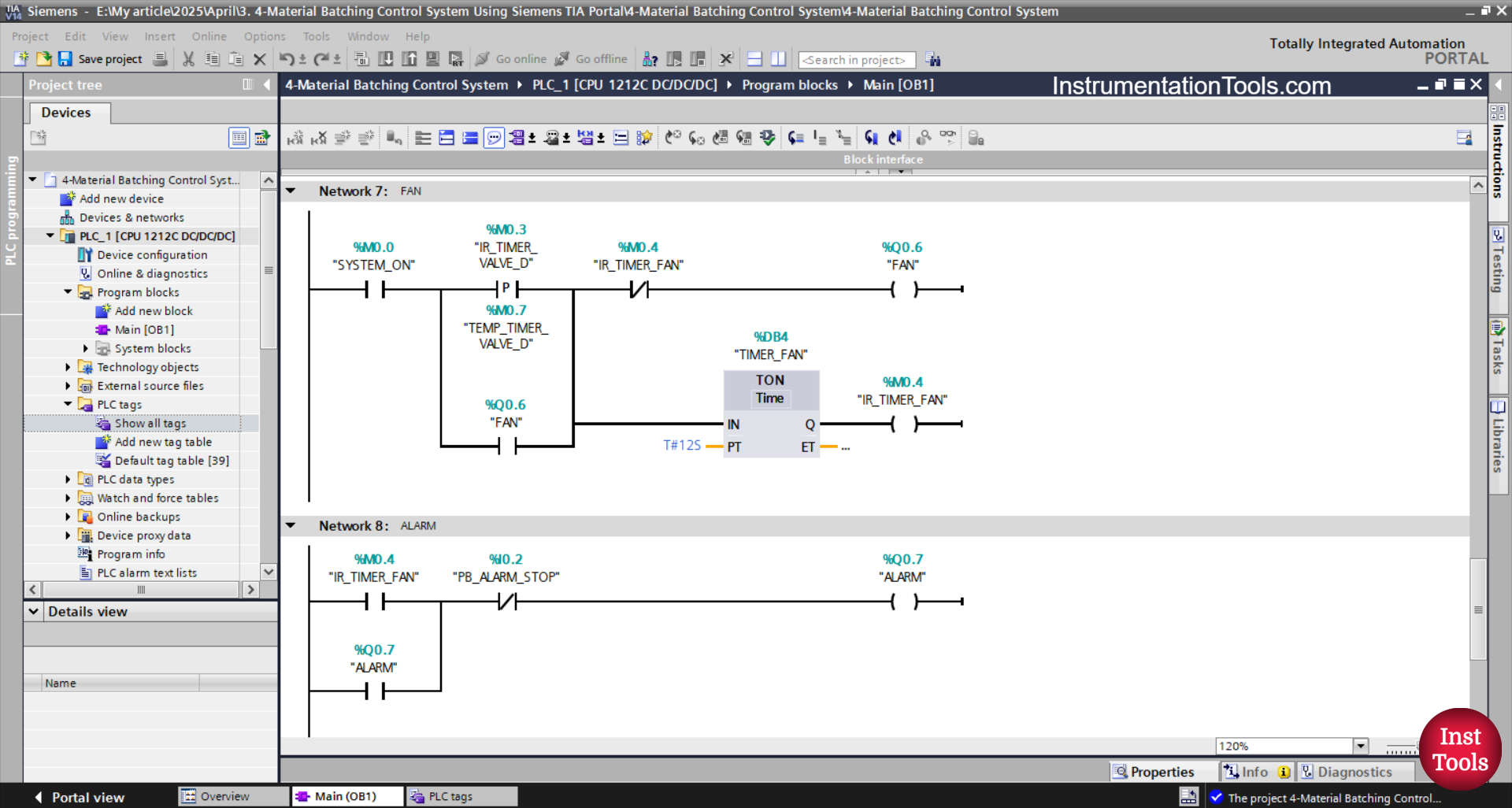
NETWORK 7 (FAN)
The output FAN (Q0.6) will be ON when the NO contact of the memory bits SYSTEM_ON (M0.0) and IR_TIMER_ VALVE_D (M0.3) are in the HIGH state. The FAN output (Q0.6) will remain ON even though the NO contact of the memory bit IR_TIMER_ VALVE_D (M0.3) is in the LOW state. Because it uses Latching.
The TIMER_ FAN (DB4) timer will start counting for 12 seconds.
After finishing counting, the output FAN (Q0.6) will be OFF because of the Interlock of the memory bit IR_TIMER_ FAN (M0.4).
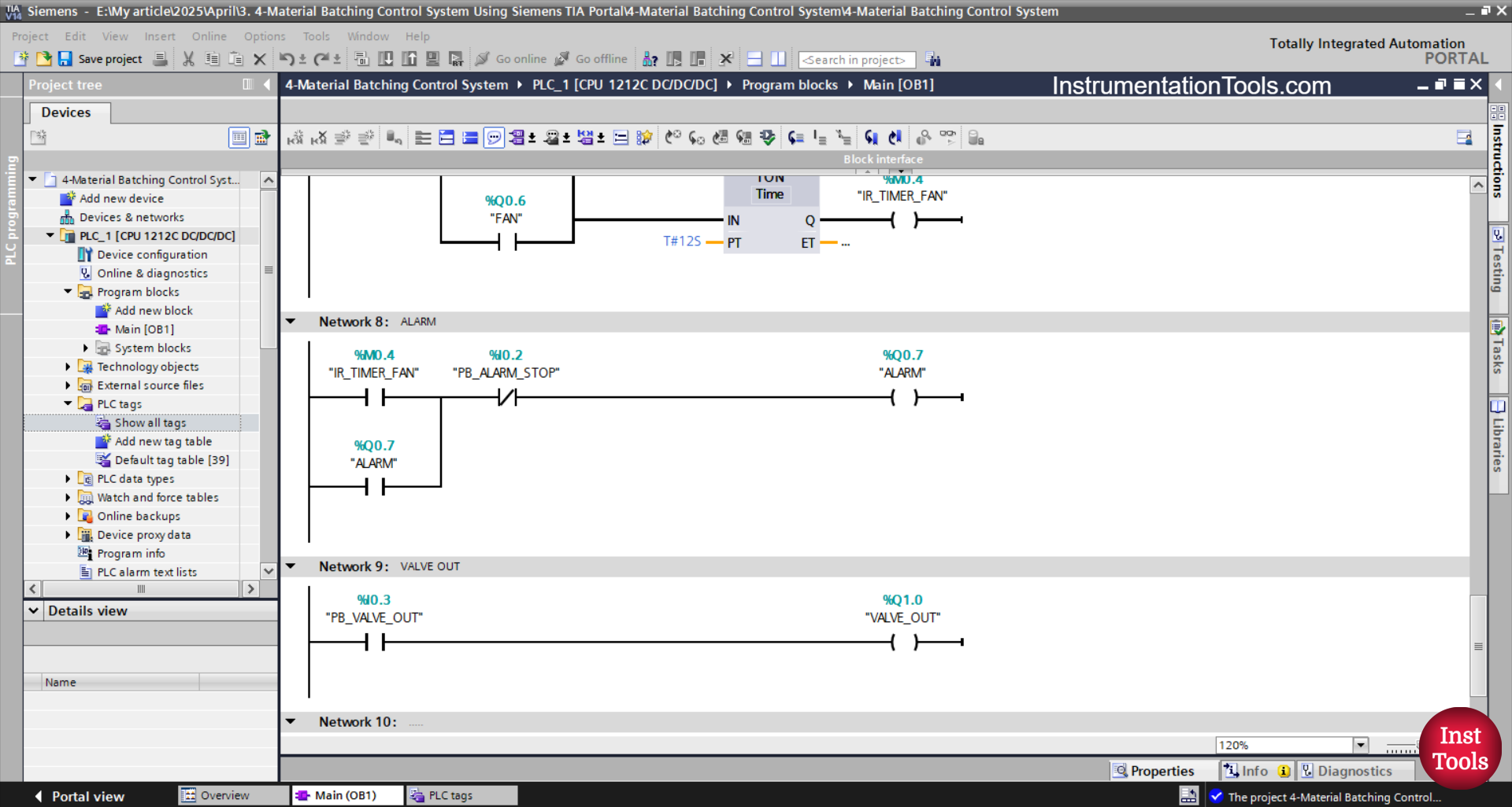
NETWORK 8 (ALARM)
The ALARM output (Q0.7) will be ON when the NO contact of the memory bit IR_TIMER_ FAN (M0.4) is in the HIGH state. The ALARM output (Q0.7) will remain ON even though the NO contact of the memory bit IR_TIMER_ FAN (M0.4) is in the LOW state. Because it uses Latching.
If the PB_ALARM_STOP (I0.2) button has been pressed, the output ALARM (Q0.7) will be OFF.
NETWORK 8 (VALVE OUT)
If the PB_VALVE_OUT (I0.3) button is pressed, the VALVE_OUT (Q1.0) output will be OPEN.
Read Next:
- PLC Programming for Liquid Filling Machine [XG5000]
- PLC Garage Door Opening and Closing Programming
- Escalator Control Based on Passenger Load in PLC
- TIA Portal: Lamps Control Using Compare Instructions
- PLC Program for Paper Cutting by Length and Count