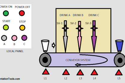
This article discusses the design of an automatic sand separator system using Mitsubishi PLC logic. The system is designed to separate sand from other materials using an automated sieving mechanism. It precisely measures the weight of the sand and regulates the sieving duration based on predefined parameters. To indicate the end of the process, the system is also equipped with an indicator alarm that activates automatically once the sieving is complete.
Program Objective
Operational Steps of the Sand Sieving System:
- Set Initial Parameters
Specify the sieving time and sand weight before starting the system. - Automatic Weighing
The system measures the sand according to the set weight; the sliding valve opens, and the weighing indicator starts measuring. - Motor Activation
Once the target weight is reached, the motor activates to drive the sieve. - Sieving Process
The sieve operates for the specified duration, and the sieved sand is automatically collected. - Open Output Valve
After sieving is complete, the output sliding valve opens to discharge the remaining material. - Residual Discharge
The sieve gate opens along with the output valve, and both close when the remaining weight is less than 3 kg. - Process Completion Alarm
The alarm turns on as an indicator that the process is complete and turns off when the system is shut down.
PLC Program for Sand Separation and Alarm Control
IO Mapping Details
| S.No. | Comment | Output(Q) | Memory Bit | Memory Word | TImers |
|---|---|---|---|---|---|
| 1 | START | M0 | |||
| 2 | STOP | M1 | |||
| 3 | SLIDING_VALVE_IN | Y000 | |||
| 4 | MOTOR_SIEVE | Y001 | |||
| 5 | SLIDING_VALVE_OUT | Y002 | |||
| 6 | GATE_SIEVE_OUT | Y003 | |||
| 7 | ALARM | Y004 | |||
| 8 | SV_WEIGHT | D0 | |||
| 9 | SV_TIME | D2 | |||
| 10 | PV_WEIGHT | D4 | |||
| 11 | TIMER_SIEVE | T0 | |||
| 12 | SYSTEM_ON | M2 | |||
| 13 | ILC_WEIGHT | M3 |
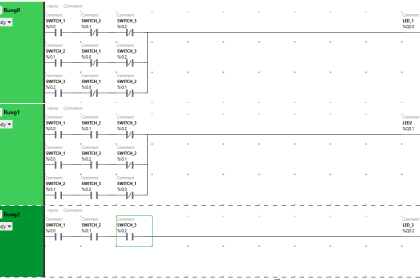
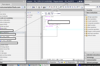
Mitsubishi PLC Based Logic
RUNG 0
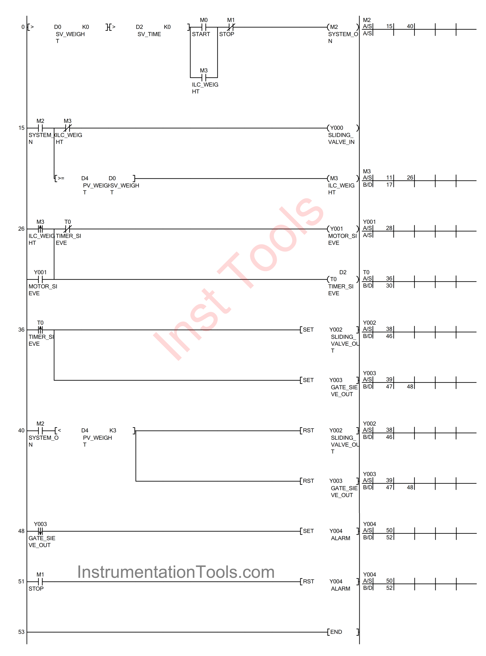
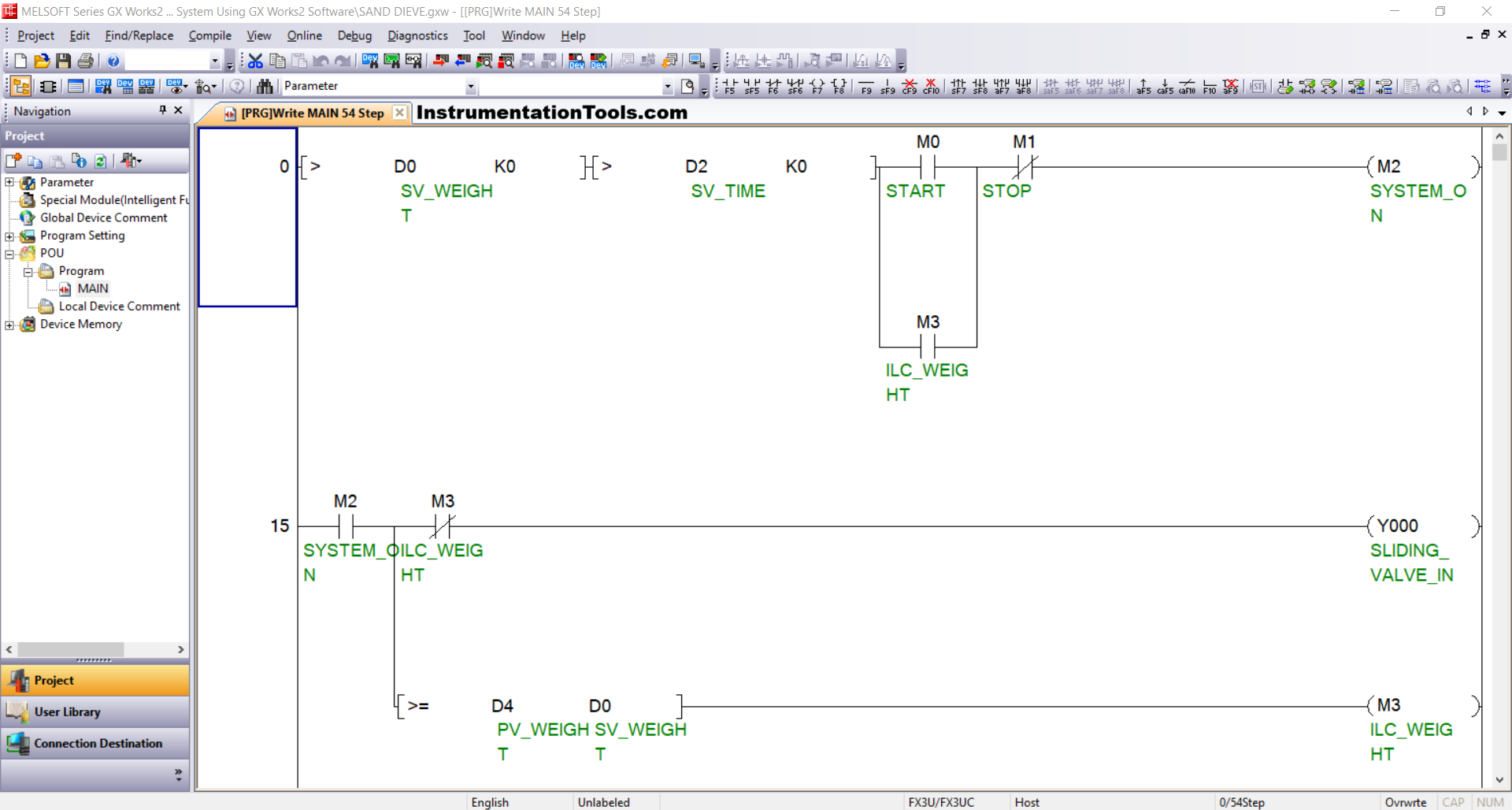
In this Rung, the memory bit SYSTEM_ON (M2) memory bit will be in a HIGH state if the START (M0) button is pressed and the value in the SV_WEIGHT (D0) and SV_TIME (D2) memory words is greater than zero “0”. Even though the START(M0) button has been released, the memory bit SYSTEM_ON (M2) will remain in a HIGH state. Because it uses Latching.
If the STOP(M1) button is pressed, the memory bit SYSTEM_ON (M2) will be in a LOW state.
RUNG 15
In this Rung, the SLIDING_VALVE_IN (Y000) output will be OPEN if the NO contact of the memory bit SYSTEM_ON (M2) is in a HIGH state.
The memory bit ILC_WEIGHT (M3) will be in HIGH state when the value in the memory word PV_WEIGHT (D4) is greater than or equal to SV_WEIGHT (D0).
The SLIDING_VALVE_IN (Y000) output will be CLOSED due to the Interlock.
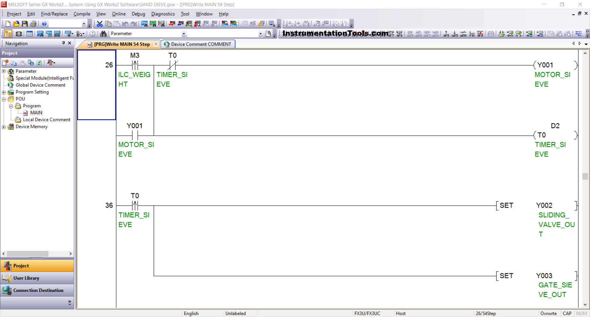
RUNG 26
In this Rung, the MOTOR_SIEVE (Y001) output will be ON, and the TIMER_SIEVE (T0) timer will start counting when the NO contact of the memory bit ILC_WEIGHT (M3) is in the HIGH state. Although the memory bit ILC_WEIGHT (M3) has been in the LOW state, the MOTOR_SIEVE (Y001) output will remain ON. Because it uses Latching.
The MOTOR_SIEVE (Y001) output will be OFF because of the interlock of the TIMER_SIEVE (T0) timer.
RUNG 36
The SLIDING_VALVE_OUT (Y002) and GATE_SIEVE_OUT (Y003) outputs will be OPEN when the NO contact of the TIMER_SIEVE (T0) timer is in the HIGH state.
Even though the NO contact of the timer TIMER_SIEVE (T0) has been in the LOW state, the output SLIDING_VALVE_OUT (Y002) and GATE_SIEVE_OUT (Y003) will remain OPEN. Because it uses the SET instruction.
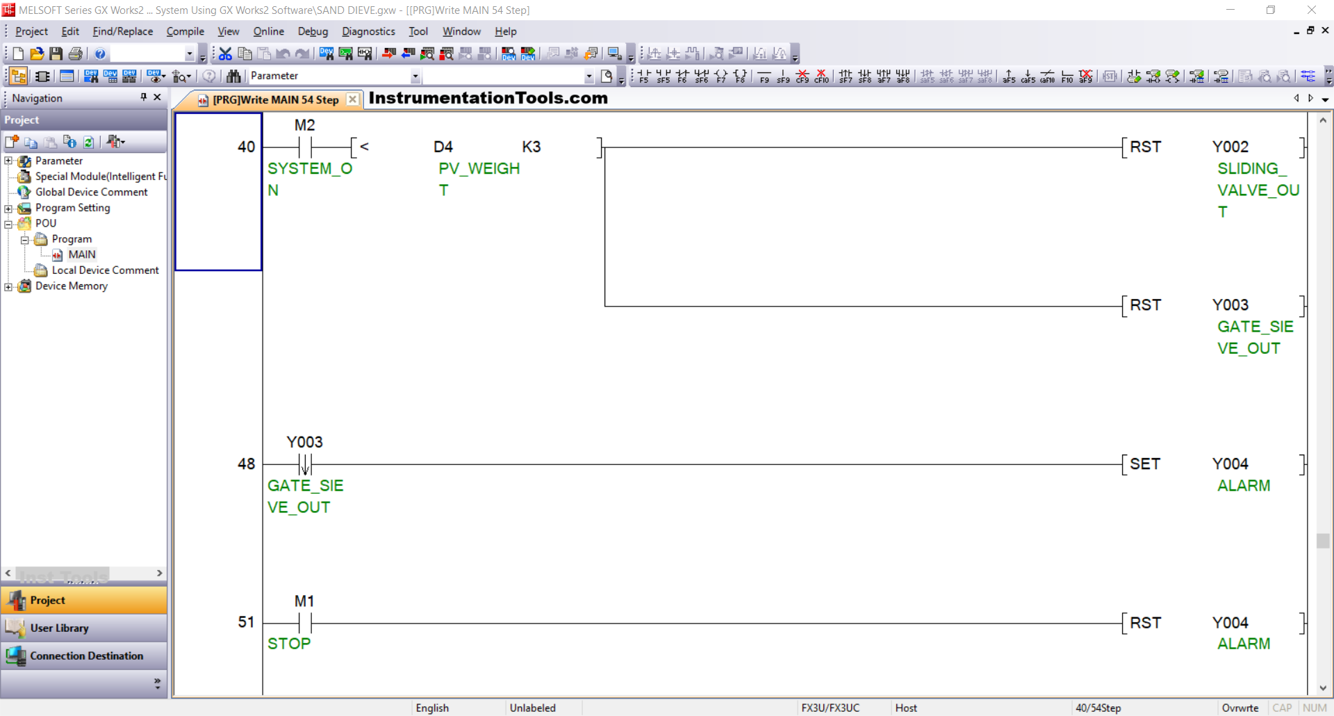
RUNG 40
In this Rung, the output SLIDING_VALVE_OUT (Y002) and GATE_SIEVE_OUT (Y003) will be CLOSED when the NO contact of the memory bit SYSTEM_ON (M2) is in the HIGH state and the value in the PV_WEIGHT memory word (D4) is less than “3”. Because it uses the RST instruction.
RUNG 48
When the NO contact of GATE_SIEVE_OUT (Y003) is in the HIGH state, the ALARM (Y004) output will be ON.
RUNG 51
If the STOP (M1) button is pressed, the ALARM (Y004) output will be OFF. Because it uses the RST instruction.
Read Next:
- Studio 5000 PLC Programming for Digital Alarms Tutorial
- Product Sticker Machine with Weighing PLC Programming
- Electrical Star-Delta System using 1 Button in PLC Program
- Highway Lights Program using RTC in PLC Programming
- Machine Indicator Lights PLC Programming Example