The matrix is controlled by a micro-controller.
For the above 16-button 4×4 matrix, 8 pins of the micro controller will be used.
The first 4 pins will be OUTPUTS and will be connected to the COLUMN wires, while the other 4 pins will be INPUTS and will be connected to the ROW wires.
The OUTPUTS of the micro-controller will NOT all have power at the same time.
The outputs will go high one by one in cycle.
During this time, it will also monitor the inputs for a signal. As long as all inputs are LOW , the Micro-controller will take no action.
Now, suppose that the operator presses the button 3C.
This button has connect the matrix col C, with the matrix row 3.
When the output C of the micro-controller becomes HIGH, the signal arrives also at the input 3 of the micro-controller, through the pressed button.
The micro-controller check the 4 inputs and detects that when the specific output (C) is high, there is a HIGH signal at the input 3.
So, this means that the input C3 is pressed!
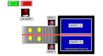
The conveyor sorting machine is widely used in the packing industries using the PLC program…
Learn the example of flip-flop PLC program for lamps application using the ladder logic to…
In this article, you will learn the STAR DELTA programming using PLC controller to start…
Lube oil consoles of rotary equipment packages in industrial process plants are usually equipped with…
Rotating equipment packages such as pumps, compressors, turbines need the lube oil consoles for their…
This article explains how to blink lights in ladder logic with a detailed explanation video…
