Inst ToolsInst ToolsInst Tools
  • Courses
  • Automation
    • PLC
    • Control System
    • Safety System
    • Communication
    • Fire & Gas System
  • Instrumentation
    • Design
    • Pressure
    • Temperature
    • Flow
    • Level
    • Vibration
    • Analyzer
    • Control Valve
    • Switch
    • Calibration
    • Erection & Commissioning
  • Interview
    • Instrumentation
    • Electrical
    • Electronics
    • Practical
  • Q&A
    • Instrumentation
    • Control System
    • Electrical
    • Electronics
    • Analog Electronics
    • Digital Electronics
    • Power Electronics
    • Microprocessor
  • Request
Search
  • Books
  • Software
  • Projects
  • Process
  • Tools
  • Basics
  • Formula
  • Power Plant
  • Root Cause Analysis
  • Electrical Basics
  • Animation
  • Standards
  • 4-20 mA Course
  • Siemens PLC Course
Reading: Making Multi Way Switches using PLC
Share
Font ResizerAa
Inst ToolsInst Tools
Font ResizerAa
  • Courses
  • Design
  • PLC
  • Interview
  • Control System
Search
  • Courses
  • Automation
    • PLC
    • Control System
    • Safety System
    • Communication
    • Fire & Gas System
  • Instrumentation
    • Design
    • Pressure
    • Temperature
    • Flow
    • Level
    • Vibration
    • Analyzer
    • Control Valve
    • Switch
    • Calibration
    • Erection & Commissioning
  • Interview
    • Instrumentation
    • Electrical
    • Electronics
    • Practical
  • Q&A
    • Instrumentation
    • Control System
    • Electrical
    • Electronics
    • Analog Electronics
    • Digital Electronics
    • Power Electronics
    • Microprocessor
  • Request
Follow US
All rights reserved. Reproduction in whole or in part without written permission is prohibited.
Inst Tools > Blog > PLC Tutorials > Making Multi Way Switches using PLC

Making Multi Way Switches using PLC

Last updated: March 4, 2021 3:51 pm
Editorial Staff
PLC Tutorials
1 Comment
Share
3 Min Read
SHARE

This is PLC Program for Making multi-way switches using PLC

Contents
Multi Way Switches using PLCSolutionList of Inputs/OutputsLadder diagram for PLC Multi-way SwitchesPLC Ladder Logic Description

We need to make multi-ways switches using PLC. Write the PLC program for the application using ladder diagram language.

Multi Way Switches using PLC
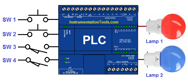
Multi Way Switches using PLC

Solution

Here we can consider two types of lamp for explanation so we can easily understand the concept.

For explanation purpose we can considered two locations and three locations of the switches installation.

Lamp 1 can be operated from the two different locations and the lamp 2 can be operated from the three different location.

List of Inputs/Outputs

List of Inputs

  • I1 :- SW1
  • I2 :- SW2
  • I15 :- SW3
  • I16 :- SW4
  • I10 :- SW5

List of Outputs

  • Q1 :- LAMP 1
  • Q2 :- LAMP 2

M memory

  • Memory coil :- M1

Ladder diagram for PLC Multi-way Switches
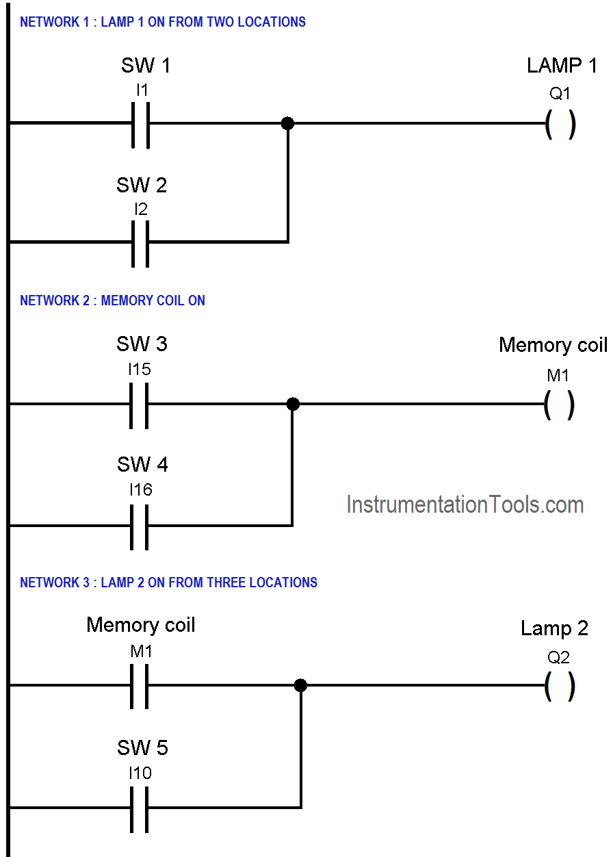
PLC Switch Control Logic

PLC Ladder Logic Description

Network 1 :-

In this network we have used OR connection of switches SW1 and SW2 so LAMP 1(Q1) can be operated from two different locations.

Network 2 :-

Here we used OR gate logic of two switches SW3 and SW4 so memory coil (M1) can be operated from two different locations.

Network 3 :-

In this network we have used OR logic for two different types of locations. Here total three locations, but out of them, two locations are on first floor and third location of the switch in remote area. So LAMP 2 (Q2) can be operated by operating any one switch from three switches.

Note :- Above application may be different from actual application. This example is only for explanation purpose only. We can implement this logic in other PLC also. This is the simple multi-way switches making using PLC, we can use this concept in other examples also.

All parameters and graphical representations considered in this example are for explanation purpose only, parameters or representation may be different in actual applications. Also all interlocks are not considered in the application.

Author : Bhavesh

If you liked this article, then please subscribe to our YouTube Channel for PLC and SCADA video tutorials.

You can also follow us on Facebook and Twitter to receive daily updates.

Read Next:

What is Ladder Diagram ?

PLC Traffic Light Control

Inductive Proximity Switch

PLC Sensor Scaling & Offset

How to Connect Proximity Switch
Don't Miss Our Updates
Be the first to get exclusive content straight to your email.
We promise not to spam you. You can unsubscribe at any time.
Invalid email address
You've successfully subscribed !

Continue Reading

PLC Energize or De-energize the Outputs based on Events
Smart Automation Solutions: PLC Logic for Stairway Lighting
LIFO Instruction in PLC
MCQ on PLC (Programmable Logic Controller)
Automatic Car Washing using PLC
Complete PLC Project: Traffic Light Auto and Manual Automation
Share This Article
Facebook Whatsapp Whatsapp LinkedIn Copy Link
Share
1 Comment
  • Md.Salim says:
    April 10, 2020 at 6:40 pm

    Thanks. …

    Reply

Leave a Reply Cancel reply

Your email address will not be published. Required fields are marked *

Stay Connected

128.3kFollowersLike
69.1kFollowersFollow
210kSubscribersSubscribe
38kFollowersFollow

Categories

Explore More

How to Create New Project Using Simatic Manager
Surface Grinding Process using PLC Program
Daily Alarm PLC Program using Real-Time Clock
Establish Communication Between Two PLC Via PROFIBUS Protocol
Basic Pumping System Application Used in Industrial Automation
Modbus Communication between PLC and Energy Meter
How to Connect PLC with SCADA System via OPC UA?
SCADA Hardware and Software

Keep Learning

PLC Program for Washing Machine

PLC Program for Washing Machine

Batch mixing process automation with Omron PLC

Automate Batch Mixing with Repeated Cycles in Omron PLC

Types of Interrupts Organization Blocks in Tia Portal

Types of Interrupt OB in Siemens Tia Portal

PLC Motor Logic

Interconnection between PLC, MCC, LCP & Pumps – Video

100 PLC Quiz Questions

100 PLC Quiz Questions : True or False

0 to 10 mA Current Loop

What is Live Zero in 4-20 mA Current Loop?

Retro-Reflective Sensor

What is a Retro-Reflective Sensor? – Principle, Applications

Siemens PLC Course for Beginners

Siemens PLC Course for Beginners: Problems and Solutions

Learn More

Single Phase Preventer Relay

Working Principle of Single Phase Preventer Relay

Armature Current in a DC Motor

DC Motor Torque

Power Systems Questions & Answers

Power Systems MCQ Series 9

Wet Leg Level Transmitter

Basics of DP Level Measurement

Independent-Voltage-Source-circuit-ideal-battery

Circuit Elements and Types of Circuits

how-to-avoid-bad-grounds

How to Avoid Bad Grounds ?

Two Tanks Filling using PLC

PLC Ladder Logic for Tanks Filling as per Priority

Difference between Compact PLC and Modular PLC

Difference between Compact PLC and Modular PLC

Menu

  • About
  • Privacy Policy
  • Copyright

Quick Links

  • Learn PLC
  • Helping Hand
  • Part Time Job

YouTube Subscribe

Follow US
All rights reserved. Reproduction in whole or in part without written permission is prohibited.
Welcome Back!

Sign in to your account

Username or Email Address
Password

Lost your password?