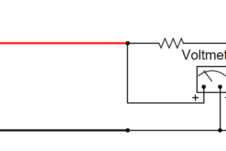
As an introduction to ladder diagrams, consider the simple wiring diagram for an electrical circuit in Figure 1.1a. The diagram shows the circuit for switching on or off an electric motor.
We can redraw this diagram in a different way, using two vertical lines to represent the input power rails and stringing the rest of the circuit between them.
Introduction to PLC Ladder Diagrams
Figure 1.1b shows the result. Both circuits have the switch in series with the motor and supplied with electrical power when the switch is closed.
The circuit shown in Figure 1.1b is termed a ladder diagram.

With such a diagram the power supply for the circuits is always shown as two vertical lines with the rest of the circuit as horizontal lines.
The power lines, or rails as they are often termed, are like the vertical sides of a ladder with the horizontal circuit lines like the rungs of the ladder.
The horizontal rungs show only the control portion of the circuit; in the case of Figure 1.1 it is just the switch in series with the motor.
Circuit diagrams often show the relative physical location of the circuit components and how they are actually wired.
With ladder diagrams no attempt is made to show the actual physical locations and the emphasis is on clearly showing how the control is exercised.

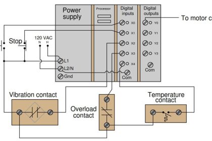
Figure 1.2 shows an example of a ladder diagram for a circuit that is used to start and stop a motor using push buttons.
In the normal state, push button 1 is open and push button 2 closed. When button 1 is pressed, the motor circuit is completed and the motor starts.
Also, the holding contacts wired in parallel with the motor close and remain closed as long as the motor is running. Thus when the push button 1 is released, the holding contacts maintain the circuit and hence the power to the motor.
To stop the motor, button 2 is pressed. This disconnects the power to the motor and the holding contacts open. Thus when push button 2 is released, there is still no power to the motor.
Thus we have a motor which is started by pressing button I and stopped by pressing button 2.
PLC Ladder Programming
A very commonly used method of programming PLCs is based on the use of ladder diagrams. Writing a program is then equivalent to drawing a switching circuit.
The ladder diagram consists of two vertical lines representing the power rails. Circuits are connected as horizontal lines, i.e., the rungs of the ladder, between these two verticals.
In drawing a ladder diagram, certain conventions are adopted:
- The vertical lines of the diagram represent the power rails between which circuits are connected. The power flow is taken to be from the left-hand vertical across a rung.
- Each rung on the ladder defines one operation in the control process.
- A ladder diagram is read from left to right and from top to bottom, Figure 1.3 showing the scanning motion employed by the PLC. The top rung is read from left to right. Then the second rung down is read from left to right and so on.

When the PLC is in its run mode, it goes through the entire ladder program to the end, the end rung of the program being clearly denoted, and then promptly resumes at the start.
This procedure of going through all the rungs of the program is termed a cycle. The end rung might be indicated by a block with the word END or RET for return, since the program promptly returns to its beginning.
- Each rung must start with an input or inputs and must end with at least one output. The term input is used for a control action, such as closing the contacts of a switch, used as an input to the PLC. The term output is used for a device connected to the output of a PLC, e.g., a motor.
- Electrical devices are shown in their normal condition. Thus a switch, which is normally open until some object closes it, is shown as open on the ladder diagram. A switch that is normally closed is shown closed.
- A particular device can appear in more than one rung of a ladder. For example, we might have a relay that switches on one or more devices. The same letters and/or numbers are used to label the device in each situation.
- The inputs and outputs are all identified by their addresses, the notation used depending on the PLC manufacturer. This is the address of the input or output in the memory of the PLC.
Figure 1.4 shows standard IEC 1131-3 symbols that are used for input and output devices. Some slight variations occur between the symbols when used in semi-graphic form and when in full graphic.
Note that inputs are represented by different symbols representing normally open or normally closed contacts. The action of the input is equivalent to opening or closing a switch. Output coils are represented by just one form of symbol.
To illustrate the drawing of the rung of a ladder diagram, consider a situation where the energizing of an output device, such as a motor, depends on a normally open start switch being activated by being closed.
The input is thus the switch and the output the motor. Figure 1.5a shows the ladder diagram.
Starting with the input, we have the normally open symbol jj for the input contacts. There are no other input devices and the line terminates with the output, denoted by the symbol ( ). When the switch is closed, i.e., there is an input, the output of the motor is activated.
Only while there is an input to the contacts is there an output. If there had been a normally closed switch j / j with the output (Figure 1.5b), then there would have been an output until that switch was opened. Only while there is no input to the contacts is there an output.

In drawing ladder diagrams the names of the associated variable or addresses of each element are appended to its symbol.
Thus Figure 1.6 shows how the ladder diagram of Figure 1.5a would appear using
(a) Mitsubishi,
(b) Siemens,
(c) Allen-Bradley,
(d) Telemecanique notations for the addresses.
Thus, Figure 1.6a indicates that this rung of the ladder program has an input from address X400 and an output to address Y430. When wiring up the inputs and outputs to the PLC, the relevant ones must be connected to the input and output terminals with these addresses.

Also Read: Why we use Normally Closed for Stop Button
If you liked this article, then please subscribe to our YouTube Channel for PLC and SCADA video tutorials.
You can also follow us on Facebook and Twitter to receive daily updates.
Read Next: