Inst ToolsInst ToolsInst Tools
  • Ask
  • Courses
  • Videos
  • Q & A
    • Interview
      • Instrumentation
      • Electronics
      • Electrical
      • Practical Questions
    • MCQ
      • Instrumentation MCQ
      • Electrical MCQ
      • Electronics MCQ
      • Control Systems MCQ
      • Analog Electronics MCQ
      • Digital Electronics MCQ
      • Power Electronics MCQ
      • Microprocessor MCQ
      • Multiple Choice Questions
  • EE
    • Electronics
      • Electronics Q & A
      • Electronic Basics
      • Electronic Devices & Circuits
      • Electronics Animation
      • Digital Electronics
    • Electrical
      • Electrical Basics
      • Electrical Q & A
      • Power Electronics
      • Electrical Machines
      • Electrical Animation
      • Power Systems
      • Switchgear & Protection
      • Transmission & Distribution
  • Measure
    • Control Valves
    • Calibration
    • Temperature
    • Pressure
    • Flow
    • Level
    • Analyzers
    • Switches
    • Vibration
    • Solenoid Valve
  • Control
    • PLC Tutorials
    • Control Systems
    • Safety Instrumented System (SIS)
    • Communication
    • Fire & Gas System
  • More
    • Design
    • Tools
    • Animation
    • Basics
    • Formulas
    • Standards
    • TextBooks
    • Common
    • Software
    • Excel Tools
    • Erection & Commissioning
    • Process Fundamentals
    • Videos
    • Books
Search
All rights reserved. Reproduction in whole or in part without written permission is prohibited.
Reading: Instrumentation Engineer’s Calibration Mistakes
Share
Notification Show More
Font ResizerAa
Inst ToolsInst Tools
Font ResizerAa
  • Courses
  • PLC Tutorials
  • Control Systems
Search
  • Ask
  • Courses
  • Videos
  • Q & A
    • Interview
    • MCQ
  • EE
    • Electronics
    • Electrical
  • Measure
    • Control Valves
    • Calibration
    • Temperature
    • Pressure
    • Flow
    • Level
    • Analyzers
    • Switches
    • Vibration
    • Solenoid Valve
  • Control
    • PLC Tutorials
    • Control Systems
    • Safety Instrumented System (SIS)
    • Communication
    • Fire & Gas System
  • More
    • Design
    • Tools
    • Animation
    • Basics
    • Formulas
    • Standards
    • TextBooks
    • Common
    • Software
    • Excel Tools
    • Erection & Commissioning
    • Process Fundamentals
    • Videos
    • Books
Follow US
All rights reserved. Reproduction in whole or in part without written permission is prohibited.
Inst Tools > Blog > Calibration > Instrumentation Engineer’s Calibration Mistakes

Instrumentation Engineer’s Calibration Mistakes

Last updated: September 1, 2019 10:47 am
Editorial Staff
Calibration
5 Comments
Share
6 Min Read
SHARE

Instrumentation Engineer’s Calibration Mistakes

Error When Attempting to Reverse the Range

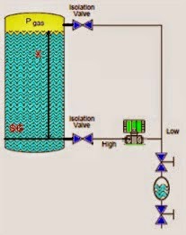
In some applications, particularly DP level, it is necessary to reverse the range such that the LRV > URV.

Contents
Instrumentation Engineer’s Calibration MistakesError When Attempting to Reverse the Range4-20 mA Range Mismatch Corrupting the range to make 4-20 mA rightCorrupting the sensor reading to make 4-20 mA rightNon-interactive zero and span

For instance, the range may have been set -87 to -1 mbar initially, but the application may actually require the range to be -1 to -87 mbar. That is the range has to be reversed:

Before :

LRV = -87 mbar  &  URV = -1 mbar

After Change :

LRV = -1 mbar  &  URV = -87 mbar

To make this range change the technician would typically make the mistake of directly enter -1 mbar for LRV which would be rejected since both URV and LRV would then be -1 mbar leaving a span of 0 mbar which would violate the minimum span.

Or, the technician would attempt to directly enter -87 mbar for URV which would also be rejected since both URV and LRV would then be – 87 mbar also violating the minimum span.

The solution is to first enter an intermediate value. For instance, setting the LRV to -40, then setting URV to -87, and lastly setting LRV to the final -1 mbar.

The same procedure applies if the sensor trim points are to be reversed.

4-20 mA Range Mismatch 

If the range set in the transmitter does not match the range in the DCS, alarms, controls, and indication will not function correctly.

Therefore it is important to document any range changes such that the correct range is set when transmitters are replaced.

Field Transmitter Range Mismatch

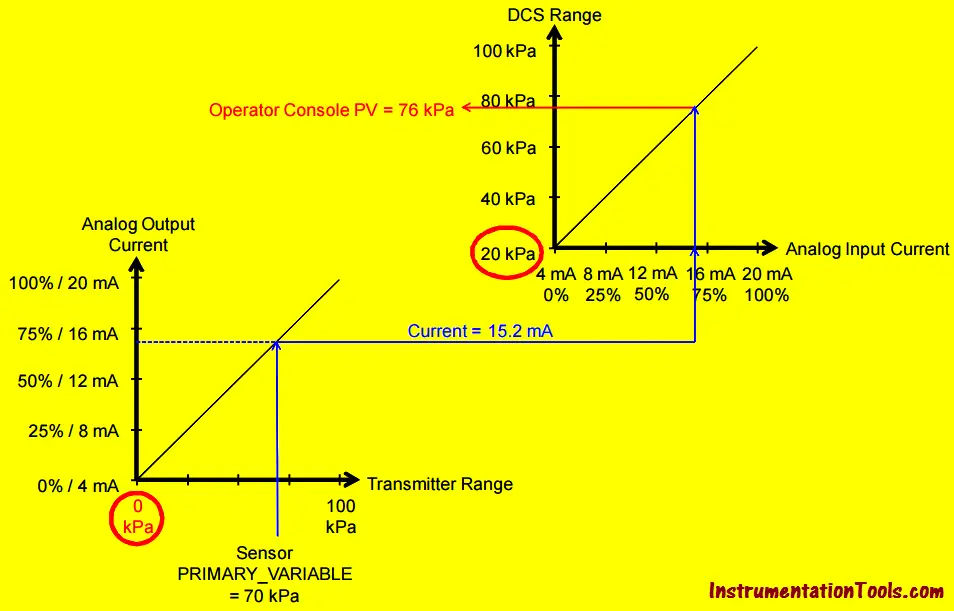
In this above example a mismatch in LRV results in erroneous indication.

Corrupting the range to make 4-20 mA right

Don’t use range setting to correct a sensor error. For example, a 4-20 mA/HART pressure transmitter ranged 0 to 100 inH2O may due to mounting position get a shift in reading of 1 inH2O.

The analog output will be 4.16 mA when no pressure is applied, making the field indicator or HMI show 1 inH2O.

A common mistake is to isolate, equalize, and vent the manifold and click the ‘Set PV LRV’ command in the device management software or handheld field communicator, or pushing the ‘zero’ and button on the device thus changing the range bringing the analog output to 4 mA.

However, checking the PV in the device management software or local transmitter indicator will reveal the sensor reading with no pressure applied is still 1 inH2O and the range is changed to 1 to 101 in H2O. Two wrongs appear to make a right.

The correct way to correct for shift or drift is to do a sensor trim.

Corrupting the sensor reading to make 4-20 mA right

Don’t use sensor trim to cancel a wet-leg. For example, a 4-20 mA/HART pressure transmitter ranged 0 to 100 inH2O may when mounted below the tank read 1 inH2O.

The analog output will be 4.16 mA when the level is zero (at the tank datum point), making the field indicator or HMI show 1 inH2O.

A common mistake is to click the ‘Zero Trim’ command in the device management software or handheld field communicator thus changing the sensor reading bringing the analog output to 4 mA.

However, if the 4-20 mA/HART pressure transmitter is isolated and vented, and the PV checked in the device management software or local transmitter indicator, it will show the sensor reading with no pressure applied is -1 inH2O. Two wrongs appear to make a right.

The correct way to cancel a wet leg is to set the range.

Non-interactive zero and span

One of the major time saving benefits that came with microprocessor-based transmitters was non-interactive zero and span:

When lower range value is set to applied input, the span (i.e. the difference between upper range value and lower range value) is maintained. That is, the upper range value is shifted by the same amount as the lower range value.

For instance, if the original range was 0-100 kPa, and lower range value is set to applied input when the applied input is 20 kPa, the new range will be 20-120 kPa, maintaining the original span of 100 kPa.

That is, the upper range value was also shifted by 20 kPa just like the lower range value.

However, if upper range value is set to applied input, the lower range value zero) is not changed.

For instance, if the original range was 0-100 kPa, and upper range value is set to applied input when the applied pressure is 80 kPa, the new range will be 0-80 kPa, maintaining the original zero of 0 kPa. That is, the lower range value was not shifted.

That is, changing the zero does not affect the span, changing the span does not affect the zero. This is non-interactive zero and span.

Article Source : Eddl

Don't Miss Our Updates
Be the first to get exclusive content straight to your email.
We promise not to spam you. You can unsubscribe at any time.
Invalid email address
You've successfully subscribed !
Bently Nevada Vibration Probes Functional Testing
Pressure Switch Calibration Procedure
Important Terms in Calibration
What is Field Transmitter Damping ?
Pressure Transmitter Calibration Procedure
Share This Article
Facebook Whatsapp Whatsapp LinkedIn Copy Link
Share
5 Comments
  • Sultan says:
    August 29, 2016 at 9:18 pm

    No Words…. Simply the Best. Excellent Articles. Thank you for sharing.

    Reply
  • Fanish says:
    December 16, 2016 at 1:48 pm

    Keep up this excellent work of sharing
    Good info

    Reply
  • Louis Reeves says:
    December 16, 2016 at 4:11 pm

    Excellent!… these are real world problems that have many technicians confused about proper calibration procedures, especially since the advent of micro-processor based instrumentation. In the old days of mostly pneumatic instrumentation, those problems didn’t exist because of the use of mechanical elevation and suppression. Today’s modern technology require a lot more training in the installation, setup and calibration of instrumentation. As a side note, I would also say that more technical education in math and physics are required as well.
    Thanks for all you do S Bharadwaj Reddy to promote the knowledge base of instrumentation technology.

    Reply
  • Otto Andrino says:
    December 19, 2016 at 9:36 pm

    Thank you for your information

    Reply
  • ANKUR BANARJI says:
    April 21, 2019 at 5:48 pm

    Thanks

    Reply

Leave a Reply Cancel reply

Your email address will not be published. Required fields are marked *

Stay Connected

128.3kFollowersLike
69.1kFollowersFollow
208kSubscribersSubscribe
38kFollowersFollow

Categories

Recent Comments

  • Kamli on Top Free PLC Software
  • Guifty Shimica on Top Non-PLC Certification Courses for Automation Professionals
  • Guifty Shimica on Top Non-PLC Certification Courses for Automation Professionals
  • MIHARITSOA Aina Sitraka on Top Non-PLC Certification Courses for Automation Professionals

Related Articles

Hybrid Level Transmitter Principle

Hybrid Level Measurement Principle, Selection, Installation, Limitations and Calibration

Smart Transmitter Calibration Tutorial Part 3

Smart Transmitter Calibration Tutorial Part 3

Why Calibration is Important

Why Calibration is Important?

Open-Tank-DP-Level-Transmitter-with-Zero-Suppression-Calibration

DP Level Transmitter with Zero Suppression Calibration

level-transmitter-calibration-procedure

Level Transmitter Calibration Procedure

Smart Transmitter Calibration Tutorial Part 2

Smart Transmitter Calibration Tutorial Part 2

Functional Testing of Control Valve Positioners

Functional Testing of Control Valve Positioners

Capacitance-Level-Transmitter

Capacitance Level Switch Calibration

More Articles

Thermocouple Reference Junction

Thermocouple Working Principle

Programmable Logic Controller (PLC) Questions and Answers

Programmable Logic Controller (PLC) Questions and Answers – 3

Electrical & Electronics Measurements Objective Questions

Electrical & Electronics Measurements Objective Questions – Set 1

Coriolis flow meter sensor coils

Coriolis Flow Meter Construction

Process vessel for measuring water level

Level Measurement Lab Exercise

Synchronous Motor Working Principle

PLC Ladder Logic Chemical Mixing Process

Chemical Mixing Process using PLC

Automating Car Parking with Advanced PLC Logic

Complex Car Parking Logic in XG5000 LS Electric PLC

Follow US
All rights reserved. Reproduction in whole or in part without written permission is prohibited.
Welcome Back!

Sign in to your account

Username or Email Address
Password

Lost your password?