Inst ToolsInst ToolsInst Tools
  • Ask
  • Courses
  • Videos
  • Q & A
    • Interview
      • Instrumentation
      • Electronics
      • Electrical
      • Practical Questions
    • MCQ
      • Instrumentation MCQ
      • Electrical MCQ
      • Electronics MCQ
      • Control Systems MCQ
      • Analog Electronics MCQ
      • Digital Electronics MCQ
      • Power Electronics MCQ
      • Microprocessor MCQ
      • Multiple Choice Questions
  • EE
    • Electronics
      • Electronics Q & A
      • Electronic Basics
      • Electronic Devices & Circuits
      • Electronics Animation
      • Digital Electronics
    • Electrical
      • Electrical Basics
      • Electrical Q & A
      • Power Electronics
      • Electrical Machines
      • Electrical Animation
      • Power Systems
      • Switchgear & Protection
      • Transmission & Distribution
  • Measure
    • Control Valves
    • Calibration
    • Temperature
    • Pressure
    • Flow
    • Level
    • Analyzers
    • Switches
    • Vibration
    • Solenoid Valve
  • Control
    • PLC Tutorials
    • Control Systems
    • Safety Instrumented System (SIS)
    • Communication
    • Fire & Gas System
  • More
    • Design
    • Tools
    • Animation
    • Basics
    • Formulas
    • Standards
    • TextBooks
    • Common
    • Software
    • Excel Tools
    • Erection & Commissioning
    • Process Fundamentals
    • Videos
    • Books
Search
All rights reserved. Reproduction in whole or in part without written permission is prohibited.
Reading: Infrared Open Path Gas Detectors Working Principle
Share
Notification Show More
Font ResizerAa
Inst ToolsInst Tools
Font ResizerAa
  • Courses
  • PLC Tutorials
  • Control Systems
Search
  • Ask
  • Courses
  • Videos
  • Q & A
    • Interview
    • MCQ
  • EE
    • Electronics
    • Electrical
  • Measure
    • Control Valves
    • Calibration
    • Temperature
    • Pressure
    • Flow
    • Level
    • Analyzers
    • Switches
    • Vibration
    • Solenoid Valve
  • Control
    • PLC Tutorials
    • Control Systems
    • Safety Instrumented System (SIS)
    • Communication
    • Fire & Gas System
  • More
    • Design
    • Tools
    • Animation
    • Basics
    • Formulas
    • Standards
    • TextBooks
    • Common
    • Software
    • Excel Tools
    • Erection & Commissioning
    • Process Fundamentals
    • Videos
    • Books
Follow US
All rights reserved. Reproduction in whole or in part without written permission is prohibited.
Inst Tools > Blog > Fire & Gas System > Infrared Open Path Gas Detectors Working Principle

Infrared Open Path Gas Detectors Working Principle

Last updated: March 14, 2018 5:33 am
Editorial Staff
Fire & Gas System
2 Comments
Share
4 Min Read
SHARE

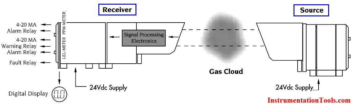
An alternative method of measuring gas concentration is based on absorption of infrared (IR) radiation at certain wavelengths as it passes through a volume of gas. Devices using this technology have a light source and a light detector and measure the light intensity at two specific wavelengths, one at an absorption (active) wavelength and one outside of the absorption (reference) wavelength. If a volume of gas passes between the source and detector, the amount of light in the active wavelength falling on the detector is reduced, while the amount of light in the reference wavelength remains unchanged. Much like the catalytic detectors, the gas concentration is determined from the relative difference between the two signals.

There are several key advantages to using IR-based detectors:

• Immune to all chemical poisons
• Does not need oxygen or air to detect gas
• Can work in continuous exposure gas environments
• Fail-to-safe technology
• Internal compensation virtually eliminates span drift

IR-based detectors can be either single-point or open path devices and, with the sophisticated optical designs currently being used, are factory calibrated and virtually maintenance free. This is particularly desirable when sensors must be located in inaccessible areas and cannot be easily calibrated on a periodic basis. Maintenance of IR detectors is typically limited to periodic cleaning of the optical windows and reflectors to ensure dependable performance. The current availability of reliable, low cost electronics and solid state IR detectors has reduced costs and made the technology feasible for many commercial applications. However, IR detectors cannot be used for the detection of hydrogen and certain other gases for which the catalytic method is suitable.

Infrared Open Path Gas Detectors Working Principle

Infrared gas detection is based on the ability of some gases to absorb IR radiation. It is well known that almost all hydrocarbons (HC) absorb IR at approximately 3.4 µm and at this region H2O and CO are not absorbed, making the system immune to humidity and atmospheric changes. It follows therefore that a dedicated spectrometer operating at that wavelength could be used to detect hydrocarbons in air. Such a system would follow the Beer-Lambert Law which states:

T=exp (-A x C x L)

Where:
T is the transmittance of IR
A is the absorption coefficient of the particular gas molecule
C is the concentration of the gas
L is the path length of the beam through the gas

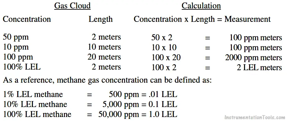
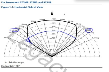
The gas concentration output for open path detectors is expressed in ppm meters (parts per million of combustible gas times the path length in meters: a highly sensitive range for detection of low level leaks) or LEL meters (a hazardous gas level).

Typical readings are as follows:

Gas Concentration Calculation

Open path IR detection offers immunity to poisons, high sensitivity gas leak detection, hazardous level gas detection, low maintenance, easy installation and fail to safe operation. However, it is not an all-encompassing answer to combustible gas detection. It offers an alternative solution to gas detection challenges and should be used in combination with point gas detection due to its limitations in targeting the specific location of gas leaks.

Don't Miss Our Updates
Be the first to get exclusive content straight to your email.
We promise not to spam you. You can unsubscribe at any time.
Invalid email address
You've successfully subscribed !
Beam Detectors Working Principle Animation
Fire and Gas System Loop Checks Procedure
Why we use End of Line (EOL) Resistor in Fire and Gas System ?
What is Gas Suppression Systems ?
Which Gases Can a Multi-Gas Detector Detect?
Share This Article
Facebook Whatsapp Whatsapp LinkedIn Copy Link
Share
2 Comments
  • Anant P. Bhise says:
    November 2, 2016 at 1:46 pm

    Send me PDF version of that to read for maintenance of gas detectors.

    Reply
  • Azumara Bobbie says:
    December 15, 2017 at 7:05 am

    Please, I need a material for the calibration of open path detectors

    Reply

Leave a Reply Cancel reply

Your email address will not be published. Required fields are marked *

Stay Connected

128.3kFollowersLike
69.1kFollowersFollow
208kSubscribersSubscribe
38kFollowersFollow

Categories

Recent Comments

  • Guifty Shimica on Top Non-PLC Certification Courses for Automation Professionals
  • Guifty Shimica on Top Non-PLC Certification Courses for Automation Professionals
  • MIHARITSOA Aina Sitraka on Top Non-PLC Certification Courses for Automation Professionals
  • Vaishnavi on Free Instrumentation Course for Trainee Engineers

Related Articles

Fire Extinguisher Operation

Basics of Fire Extinguisher

Argonite Fire Suppression System Animation

Argonite Fire Suppression System Working Principle

Fire Detectors Working Principle

Basics of Fire Detection and Alarm System

Carbon Monoxide Gas Hazards

Carbon Monoxide Gas Hazards

What is Photoionization Detector (PID)

What is Photoionization Detector (PID)?

Gases LEL and UEL

What is Lower Explosive Limit & Upper Explosive Limit ?

Quartzoid Bulb Detector Working Principle

Fire Water Sprinklers Working Principle

Gas Detection System Abbreviations

Gas Detection System Abbreviations

More Articles

NACE Standards - MR0103 Vs MR0175

NACE Standards – MR0103 Vs MR0175

Dew Point Method Humidity Measurement

Humidity Measurement Principle

Difference Between the Control Valve and Shut-off Valve

Difference Between the Control Valve and Shut-off Valve

Good and Bad Wiring Practices

Instrumentation loop Diagram

Instrumentation Loop Diagrams

Viscosity Measurement Objective Questions

Viscosity Measurement Objective Questions

Time Response Analysis

Time Response of First Order Systems Objective Questions

Level Loop Troubleshooting

Identify Faults in PID Control Loop

Follow US
All rights reserved. Reproduction in whole or in part without written permission is prohibited.
Welcome Back!

Sign in to your account

Username or Email Address
Password

Lost your password?