Control Systems

Industrial Automation System Architecture Reference Model

Architectures represented are based on the IEC 62443 Industrial Automation and Control Systems (IACS) architecture reference model. The basic model consists of 5 levels.

System Architecture

Industrial Automation Architecture reference model

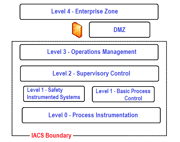
Figure 1: An Architecture reference model

Level 0:

It is the Process or equipment under control

Level 1:

It includes the Controllers/PLCs that provide basic control, safety and protection functions

Level 2:

It includes supervisory control functions and includes devices such as HMIs, Operating workstations, Engineering Workstations, Historians, Application Servers, Engineering Databases, etc.

Level 3:

It includes the operations management functions such as domain controller, backup server, antivirus and patch management, etc.

Level 4:

It refers to the Enterprise systems

Architecture Diagram Notations

  • The architecture diagrams show a very simplistic view of system architectures.
  • These architecture diagrams illustrate specific ways to perform remote access.
  • The local “IACS” network is represented simplistically to ease the understanding (the actual internal IACS architecture will vary and specific integration and interfaces between the diverse IACS usually required in most implementation is not included or represented in these diagrams).
  • Dataflows between the different functions are represented by arrows. The direction of the arrows show the outbound or inbound characteristic of the dataflow, but do not represent network sessions.
  • HMI is used as a generic term to refer to any Human Machine Interface or workstation (Operator, maintenance or engineering workstations, for BPCS, SIS, or Packages).
  • Local station refers to any workstation or server located at the production site that is used to transfer data or is accessed from a remote site.
  • The DMZ firewall is represented as a single symbol but can be implemented as a pair of physical firewalls.
  • The tunnel shown on the diagram refers to a secure tunnel, that can be set up with different technical solutions (e.g., IPSec).
  • These architecture Diagrams do not show the full detail of all possible types of local networks. Depending on the system vendor solution, some networks that are represented as the separate networks (such as control and HMI network) may be a single network.

Source: International Association of Oil & Gas Producers

Acknowledgments: IOGP Instrumentation and Automation Standards Subcommittee (IASSC) Remote Operating Centres Task Force.

Read Next:

You've successfully subscribed !
Share

Recent Articles

  • PLC Tutorials

PLC Panel and MCC Panel Interface Signals

The PLC panel and MCC panel interface signals are start, stop, run feedback, trip, local…

4 days ago
  • PLC Tutorials

Shutter Door Control using Motor and Limit Switches

 In this article, we are going to discuss about shutter door control using induction motor…

6 days ago
  • Electrical Basics

Electrical Drives – Modes, Types, Speed Control Applications

Electrical Drives control the motion of electric motors. Motion control is required in industrial and…

6 days ago
  • PLC Tutorials

PLC Ladder Logic Design: Control 3 Motors with Toggle Switch

PLC ladder logic design to control 3 motors with toggle switch and explain the program…

3 weeks ago
  • PLC Tutorials

VFD Simulator Download – Free Yaskawa V1000 Software

VFD simulator download: Master the online tool from the Yaskawa V1000 & programming software for…

6 days ago
  • PLC Tutorials

Conveyor Sorting Machine PLC Program with Calculation Function

The conveyor sorting machine is widely used in the packing industries using the PLC program…

7 hours ago