Inst ToolsInst ToolsInst Tools
  • Courses
  • Automation
    • PLC
    • Control System
    • Safety System
    • Communication
    • Fire & Gas System
  • Instrumentation
    • Design
    • Pressure
    • Temperature
    • Flow
    • Level
    • Vibration
    • Analyzer
    • Control Valve
    • Switch
    • Calibration
    • Erection & Commissioning
  • Interview
    • Instrumentation
    • Electrical
    • Electronics
    • Practical
  • Q&A
    • Instrumentation
    • Control System
    • Electrical
    • Electronics
    • Analog Electronics
    • Digital Electronics
    • Power Electronics
    • Microprocessor
  • Request
Search
  • Books
  • Software
  • Projects
  • Process
  • Tools
  • Basics
  • Formula
  • Power Plant
  • Root Cause Analysis
  • Electrical Basics
  • Animation
  • Standards
  • 4-20 mA Course
  • Siemens PLC Course
Reading: What is Indicator ?
Share
Font ResizerAa
Inst ToolsInst Tools
Font ResizerAa
  • Courses
  • Design
  • PLC
  • Interview
  • Control System
Search
  • Courses
  • Automation
    • PLC
    • Control System
    • Safety System
    • Communication
    • Fire & Gas System
  • Instrumentation
    • Design
    • Pressure
    • Temperature
    • Flow
    • Level
    • Vibration
    • Analyzer
    • Control Valve
    • Switch
    • Calibration
    • Erection & Commissioning
  • Interview
    • Instrumentation
    • Electrical
    • Electronics
    • Practical
  • Q&A
    • Instrumentation
    • Control System
    • Electrical
    • Electronics
    • Analog Electronics
    • Digital Electronics
    • Power Electronics
    • Microprocessor
  • Request
Follow US
All rights reserved. Reproduction in whole or in part without written permission is prohibited.
Inst Tools > Blog > Control Systems > What is Indicator ?

What is Indicator ?

Last updated: July 29, 2019 4:25 am
Editorial Staff
Control Systems
No Comments
Share
4 Min Read
SHARE

One common “auxiliary” instrument is the indicator, the purpose of which is to provide a human readable indication of an instrument signal. Sometimes process transmitters are not equipped with readouts for whatever variable they measure: they just transmit a standard instrument signal (4 to 20 mA, etc.) to another device.

Contents
IndicatorNumerical Plus Bar Graph IndicatorDisplay IndicatorField Mounted Indicator

In some cases we may need extra local display for showing the process value to the operators, examples like an level transmitter installed on a big tank & level value will be shown to operator at the bottom of the tank using indicators or loop powered devices.

An indicator gives a human operator a convenient way of seeing what the output of the transmitter is without having to connect test equipment. Moreover, indicators may be located far from their respective transmitters, providing readouts in locations more convenient than the location of the transmitter itself.

Indicator

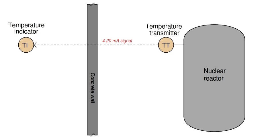
An example where remote indication would be practical is shown here, in a nuclear reactor temperature measurement system:

Loop Power Indicators

It would be unsafe for human beings to approach the nuclear reactor when it is in full-power operation, due to the strong radiation flux it emits.

The temperature transmitter is built to withstand the radiation, though, and it transmits a 4 to 20 milliamp electronic signal to an indicator (Loop powered device) located on the other side of a thick concrete wall blocking the reactor’s radiation, where it is safe for human occupancy.

There is nothing preventing us from connecting multiple indicators, at multiple locations, to the same 4 to 20 milliamp signal wires coming from the temperature transmitter.

This allows us to display the reactor temperature in as many locations as we desire, since there is no absolute limit on how far we may conduct a DC milliamp signal along copper wires.

Note : Only criteria we have is to maintain the minimum loop voltage otherwise loop current will be reduced & indicate wrong values.

Numerical Plus Bar Graph Indicator

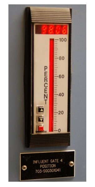
A numerical-plus-bargraph indicator appears in this next photograph, mounted in the face of a metal panel inside of a control room:

Field Indicators

This particular indicator shows the position of a flow-control gate in a wastewater treatment facility, both by numerical value (98.06%) and by the height of a bargraph (very near full open – 100%).

It is directly wired in series with the same 4-20 milliamp current signal sent to the gate actuator.

Display Indicator

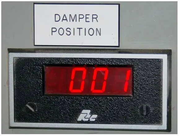
A less sophisticated style of panel-mounted indicator shows only a numeric display, such as this unit shown here:

Field Indicators in industrial instrumentation

Indicators may also be used in “field” (process) areas to provide direct indication of measured variables if the transmitter device lacks a human-readable indicator of its own.

Field Mounted Indicator

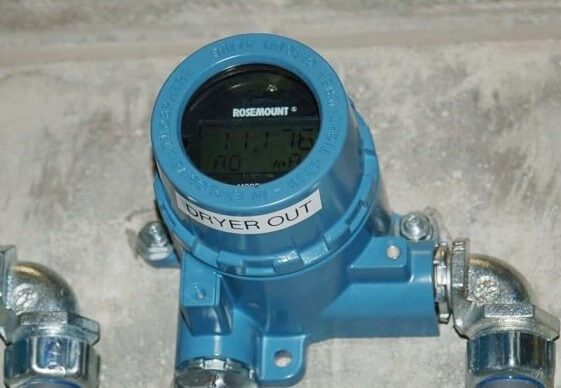
The following photograph shows a field-mounted indicator, operating directly from the electrical power available in the 4-20 mA loop. The numerical display of this indicator uses LCD technology rather than red-glowing LEDs, in order to use less electrical power:
Transmitter Indicators

Articles You May Like :

What is Feedback ?

Control Loop Questions

Why 4-20 mA popular ?

High-frequency Cables

Different Level Indicators

Don't Miss Our Updates
Be the first to get exclusive content straight to your email.
We promise not to spam you. You can unsubscribe at any time.
Invalid email address
You've successfully subscribed !

Continue Reading

Heuristic PID Tuning Procedure
What is a Floating License? – Automation Software Systems
Open Loop and Closed Loop Animation
Proportioning Feedforward action
On/off Control Theory
How to Prevent Ground Loops in Analog Circuits?
Share This Article
Facebook Whatsapp Whatsapp LinkedIn Copy Link
Share
Leave a Comment

Leave a Reply Cancel reply

Your email address will not be published. Required fields are marked *

Stay Connected

128.3kFollowersLike
69.1kFollowersFollow
210kSubscribersSubscribe
38kFollowersFollow

Categories

Explore More

Chemical Reactor Temperature Control System
What is a Network Connector? – Types of Connectors
Steady-State Process Gain
PID Controller Response with different Input Signals
Project Planning and Implementation of PLC or DCS Control System
Supervisory Control
How to choose between PLC and DCS Systems ?
Technical Evaluation for DCS and ESD – Distributed Control System

Keep Learning

Signal Isolator

What is a Signal Isolator? Principle, Advantages, Disadvantages

Liquid Level Switch Control Pump and Lamp

Liquid Level Switch Control Pump and Lamp

Electrical Ground Loop

How to Solve Electrical Ground Loop Problems?

Stroke Checking Procedure for GCV, SRV, IGV, and LFBV

Stroke Checking Procedure for GCV, SRV, IGV, and LFBV

Industrial Automation and Control

100+ Questions and Answers on Industrial Automation and Control

Grounding Electronic Equipment

Importance of Grounding Electronic Equipment

Client - server network system

Network Operating System

Earthing Calculations

Electrical Earthing Calculations

Learn More

Difference Between Open Circuit and Close Circuit

Difference Between Open Circuit and Close Circuit

Transformer voltage and turns ratio

Transformer Current Ratio

DC Generator

DC Generator

Two-Liquid Manometer Principle

Two-Liquid Manometer Principle

Omron PLC painting program

Product Painting PLC Program using Omron CX-Programmer

Power Electronics Objective Questions

AC Voltage Controllers Objective Questions

PLC Interview Questions and Answers

PLC Interview Questions and Answers

Fiber Optics Objective Questions and Answers

Fiber Optics Objective Questions and Answers

Menu

  • About
  • Privacy Policy
  • Copyright

Quick Links

  • Learn PLC
  • Helping Hand
  • Part Time Job

YouTube Subscribe

Follow US
All rights reserved. Reproduction in whole or in part without written permission is prohibited.
Welcome Back!

Sign in to your account

Username or Email Address
Password

Lost your password?