Inst ToolsInst ToolsInst Tools
  • Courses
  • Automation
    • PLC
    • Control System
    • Safety System
    • Communication
    • Fire & Gas System
  • Instrumentation
    • Design
    • Pressure
    • Temperature
    • Flow
    • Level
    • Vibration
    • Analyzer
    • Control Valve
    • Switch
    • Calibration
    • Erection & Commissioning
  • Interview
    • Instrumentation
    • Electrical
    • Electronics
    • Practical
  • Q&A
    • Instrumentation
    • Control System
    • Electrical
    • Electronics
    • Analog Electronics
    • Digital Electronics
    • Power Electronics
    • Microprocessor
  • Request
Search
  • Books
  • Software
  • Projects
  • Process
  • Tools
  • Basics
  • Formula
  • Power Plant
  • Root Cause Analysis
  • Electrical Basics
  • Animation
  • Standards
  • 4-20 mA Course
  • Siemens PLC Course
Reading: Inclined-limb Manometer Principle
Share
Font ResizerAa
Inst ToolsInst Tools
Font ResizerAa
  • Courses
  • Design
  • PLC
  • Interview
  • Control System
Search
  • Courses
  • Automation
    • PLC
    • Control System
    • Safety System
    • Communication
    • Fire & Gas System
  • Instrumentation
    • Design
    • Pressure
    • Temperature
    • Flow
    • Level
    • Vibration
    • Analyzer
    • Control Valve
    • Switch
    • Calibration
    • Erection & Commissioning
  • Interview
    • Instrumentation
    • Electrical
    • Electronics
    • Practical
  • Q&A
    • Instrumentation
    • Control System
    • Electrical
    • Electronics
    • Analog Electronics
    • Digital Electronics
    • Power Electronics
    • Microprocessor
  • Request
Follow US
All rights reserved. Reproduction in whole or in part without written permission is prohibited.
Inst Tools > Blog > Pressure Measurement > Inclined-limb Manometer Principle

Inclined-limb Manometer Principle

Last updated: September 13, 2017 6:18 am
Editorial Staff
Pressure Measurement
No Comments
Share
0 Min Read
SHARE

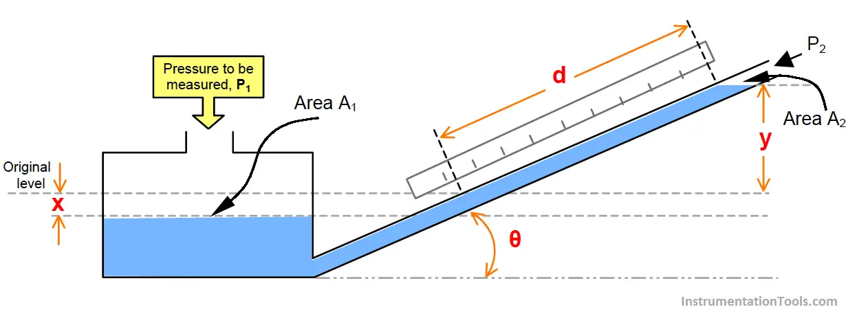
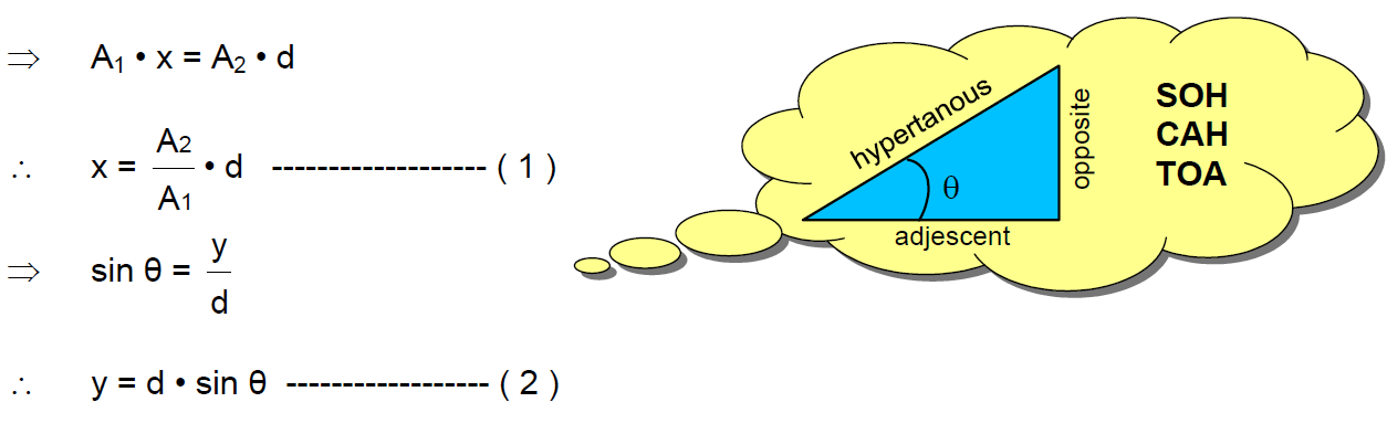
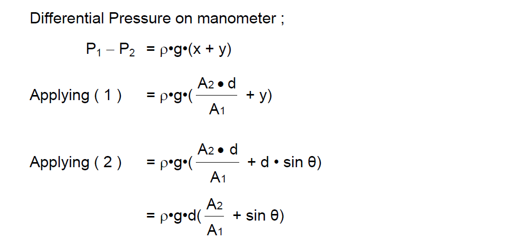
This design of manometer is shown on the figure. As the name ” Inclined-Limb Manometer ” suggests, the manometer limb is inclined at an angle to the horizontal. The effect of inclining the limb is to make the manometer more sensitive than the well type, allowing the more accurate measurement of a lower range of pressures. Principle will be same as Well type Manometer.

Inclined-limb Manometer Principle

Inclined-limb Manometer Formula

Inclined-limb Manometer Formula - 2

Don't Miss Our Updates
Be the first to get exclusive content straight to your email.
We promise not to spam you. You can unsubscribe at any time.
Invalid email address
You've successfully subscribed !

Continue Reading

Functions of Pressure Detectors
All About Instrumentation Impulse Lines
Helix and Spiral Tubes – Pressure Sensor
Pressure Gauges Zero Adjustment
Electronic Pressure Sensors Principle
Troubleshooting Fluid Systems Pressure Changes
Share This Article
Facebook Whatsapp Whatsapp LinkedIn Copy Link
Share
Leave a Comment

Leave a Reply Cancel reply

Your email address will not be published. Required fields are marked *

Stay Connected

128.3kFollowersLike
69.1kFollowersFollow
210kSubscribersSubscribe
38kFollowersFollow

Categories

Explore More

Impulse Line – Purpose & Tapping Point Location
Semi Conductor or Piezo Resistive Strain Gauge Principle
Inductance Type Pressure Transducers Principle
Why are Impulse Lines often Installed in a Sloping Manner?
Differential Pressure Switch Principle
Bourdon Tube Pressure Gauge
Unbonded Strain Gauge Principle
Pressure Transmitter Circuit

Keep Learning

Pressure Gauge with Syphons

Pressure Gauge Syphons Principle

Strain Gauge Pressure Transducer

Resistance Type Pressure Transducers Principle

gauge’s bourdon tube

Pressure Gauges : Remote and Chemical Seals

Pressure Transmitter Calibration Setup

Pressure Transmitter Preventive Maintenance

Gauge Display Scale

How to Read Gauge Analog Scales

Pressure Measurement Interview Questions

Interview Questions on Pressure Measurement

Pressure Gauge Calibration according to Standard DKD-R-6-1

Pressure Gauge Calibration according to Standard DKD-R-6-1

U tube Manometer Working

Basics of Pressure

Learn More

PLC Modbus Communication

Introduction to Modbus – Reading and Writing Data

Displacer Level Sensor Working Animation

Displacer Level Sensor Working Animation

Digital Transducers Objective Questions

Digital Transducers Objective Questions

Stilling wells

Stilling Wells for Level Measurement

Configure the Instruments in Flow Control Loop

Configure the Instruments in Flow Control Loop

Guided Wave Radar Level Transmitter Compensation

Guided Wave Radar Level Sensor Pressure and Temperature Effects

Fire Extinguishers Mock Test

Fire Extinguishers Mock Test

Temperature Control System Example

Chemical Reactor Temperature Control System

Menu

  • About
  • Privacy Policy
  • Copyright

Quick Links

  • Learn PLC
  • Helping Hand
  • Part Time Job

YouTube Subscribe

Follow US
All rights reserved. Reproduction in whole or in part without written permission is prohibited.
Welcome Back!

Sign in to your account

Username or Email Address
Password

Lost your password?