Inst ToolsInst ToolsInst Tools
  • Courses
  • Automation
    • PLC
    • Control System
    • Safety System
    • Communication
    • Fire & Gas System
  • Instrumentation
    • Design
    • Pressure
    • Temperature
    • Flow
    • Level
    • Vibration
    • Analyzer
    • Control Valve
    • Switch
    • Calibration
    • Erection & Commissioning
  • Interview
    • Instrumentation
    • Electrical
    • Electronics
    • Practical
  • Q&A
    • Instrumentation
    • Control System
    • Electrical
    • Electronics
    • Analog Electronics
    • Digital Electronics
    • Power Electronics
    • Microprocessor
  • Request
Search
  • Books
  • Software
  • Projects
  • Process
  • Tools
  • Basics
  • Formula
  • Power Plant
  • Root Cause Analysis
  • Electrical Basics
  • Animation
  • Standards
  • 4-20 mA Course
  • Siemens PLC Course
Reading: How to Measure Duty Cycle using Multimeter
Share
Font ResizerAa
Inst ToolsInst Tools
Font ResizerAa
  • Courses
  • Design
  • PLC
  • Interview
  • Control System
Search
  • Courses
  • Automation
    • PLC
    • Control System
    • Safety System
    • Communication
    • Fire & Gas System
  • Instrumentation
    • Design
    • Pressure
    • Temperature
    • Flow
    • Level
    • Vibration
    • Analyzer
    • Control Valve
    • Switch
    • Calibration
    • Erection & Commissioning
  • Interview
    • Instrumentation
    • Electrical
    • Electronics
    • Practical
  • Q&A
    • Instrumentation
    • Control System
    • Electrical
    • Electronics
    • Analog Electronics
    • Digital Electronics
    • Power Electronics
    • Microprocessor
  • Request
Follow US
All rights reserved. Reproduction in whole or in part without written permission is prohibited.
Inst Tools > Blog > Electronic Basics > How to Measure Duty Cycle using Multimeter

How to Measure Duty Cycle using Multimeter

Last updated: April 27, 2017 4:21 am
Editorial Staff
Electronic Basics
No Comments
Share
3 Min Read
SHARE

Duty cycle basics

  • Duty cycle is the ratio of time a load or circuit is ON to the time a load or circuit is OFF. A load that is turned ON and OFF several times per second has a duty cycle.
  • Why do this? Many loads are rapidly cycled on and off by a fast-acting electronic switch to accurately control output power at the load. Lamp brightness, heating element outputs and magnetic strength of a coil can be controlled by duty cycle.
  • Duty cycle is measured in percentage of ON time. Example: A 60% duty cycle is a signal that is on 60% of the time and off 40% of the time.
  • An alternate way to measure duty cycle is dwell, measured in degrees instead of percent.
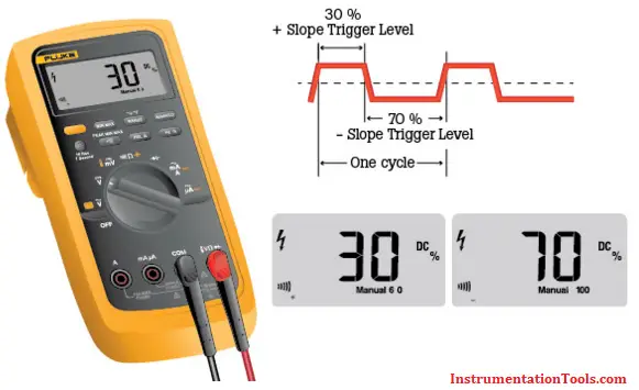
  • When measuring duty cycle, a digital multimeter displays the amount of time the input signal is above or below a fixed trigger level – the fixed level at which the multimeter counter is triggered to record frequency. Slope is the waveform edge on which the trigger level is selected.
  • The percent of time above the trigger level is displayed if the positive trigger slope is selected. Conversely, the percent of time below the trigger level is displayed if the negative trigger slope is selected. The slope selected is indicated by a positive (+) or negative (-) symbol in the display. Most multimeters default to display the positive trigger slope; the negative trigger slope is usually selected by pressing an additional button. Refer to a DMM’s user manual for specifics.

Measure Duty Cycle using Multimeter

Contents
Duty cycle basicsHow to measure duty cycle

How to measure duty cycle

  1. Set the digital multimeter (DMM) to measure frequency. The steps can vary by meter. Usually a multimeter’s dial will be turned to dc V and the Hz button is pressed. The DMM is ready to measure duty cycle when a percent sign (%) appears in the right side of the multimeter’s display.
  2. First insert the black test lead into the COM jack.
  3. Then insert the red lead into the V Ω jack. When finished, remove the leads in reverse order: red first, then black.
  4. Connect the test leads to the circuit to be tested.
  5. Read the measurement in the display. A positive symbol (+) indicates POSITIVE time percent voltage measurement. A negative symbol (-) indicates NEGATIVE time percent voltage measurement.
    Note: A positive reading typically indicates a circuit’s ON time and a negative reading its OFF time. On occasion a negative portion of the signal can create an ON signal.
  6. Press the beeper button to toggle between POSITIVE time and NEGATIVE time percent voltage measurement. Note: The button used varies by digital multimeter. Refer to you model’s user manual for specific instructions.

Source : Fluke

Also Read: Measure AC Voltage using Multimeter

Don't Miss Our Updates
Be the first to get exclusive content straight to your email.
We promise not to spam you. You can unsubscribe at any time.
Invalid email address
You've successfully subscribed !

Continue Reading

How to Identify the Transistor Terminals
Basics of Voltage Regulator
Factors Affecting Inductance
How to measure frequency using Multimeter
Electrical Static Grounding Techniques
Power Supply Circuit Fault Analysis
Share This Article
Facebook Whatsapp Whatsapp LinkedIn Copy Link
Share
Leave a Comment

Leave a Reply Cancel reply

Your email address will not be published. Required fields are marked *

Stay Connected

128.3kFollowersLike
69.1kFollowersFollow
210kSubscribersSubscribe
38kFollowersFollow

Categories

Explore More

Types of Noise in Electronics
Clamp Meters Working Principle
Difference Between LED and LCD
Difference Between LED and LDR
Zener Diode Voltage Regulators
What is Cathode Ray oscilloscope ?
How to Measure capacitance using Multimeter
What is an Inductor? – Types of Inductors

Keep Learning

Measure AC Voltage using Multimeter

How to Measure AC Voltage using Multimeter

Difference Between Electrical and Electronic Devices

Difference Between Electrical and Electronic Devices

How to Test a Transistor

How to Test a Transistor ?

Clamp Meter

Things to Know When Measuring Current

How to Test Diodes Using Multimeter

How to Test Diodes Using Multimeter

Switched Mode Power Supply (SMPS)

How does SMPS Works? – Switched Mode Power Supply

Difference between Analog Signal and Digital Signal

What are Analog and Digital Signals? Differences, Examples

How are Silicon Chips Disposed?

How are Silicon Chips Disposed?

Learn More

Career Scope in Electrical Engineering

Career Scope in Electrical Engineering

Ladder Logic for Stair-Case wiring using Toggle Switches

Ladder Logic for Stair-Case wiring using Toggle Switches

potentiometric level measurement principle

Potentiometric Level Measurement Principle

Automation in Mining Industry

Industrial Automation in the Mining Industry

Digital Electronics Multiple Choice Questions

Design a flip-flop using other flip-flops Questions

What is a Magnetic Field

Difference Between Electric Field and Magnetic Field

Top 20 Service Business Opportunities in the Instrumentation Industry

Top 20 Instrumentation Service Business Opportunities in the Industry

HART Multidrop Network

HART Communication Tutorial Part 2

Menu

  • About
  • Privacy Policy
  • Copyright

Quick Links

  • Learn PLC
  • Helping Hand
  • Part Time Job

YouTube Subscribe

Follow US
All rights reserved. Reproduction in whole or in part without written permission is prohibited.
Welcome Back!

Sign in to your account

Username or Email Address
Password

Lost your password?