Inst ToolsInst ToolsInst Tools
  • Courses
  • Automation
    • PLC
    • Control System
    • Safety System
    • Communication
    • Fire & Gas System
  • Instrumentation
    • Design
    • Pressure
    • Temperature
    • Flow
    • Level
    • Vibration
    • Analyzer
    • Control Valve
    • Switch
    • Calibration
    • Standards
    • Basics
    • Formula
    • Erection & Commissioning
    • Process Fundamentals
    • Root Cause Analysis
  • Interview
    • Instrumentation
    • Electrical
    • Electronics
    • Practical
  • Q&A
    • Instrumentation
    • Control System
    • Electrical
    • Electronics
    • Analog Electronics
    • Digital Electronics
    • Power Electronics
    • Microprocessor
Search
All rights reserved. Reproduction in whole or in part without written permission is prohibited.
Reading: How to Measure AC Voltage using Multimeter
Share
Notification Show More
Font ResizerAa
Inst ToolsInst Tools
Font ResizerAa
  • Courses
  • PLC
  • Control Systems
Search
  • Courses
  • Automation
    • PLC
    • Control System
    • Safety System
    • Communication
    • Fire & Gas System
  • Instrumentation
    • Design
    • Pressure
    • Temperature
    • Flow
    • Level
    • Vibration
    • Analyzer
    • Control Valve
    • Switch
    • Calibration
    • Standards
    • Basics
    • Formula
    • Erection & Commissioning
    • Process Fundamentals
    • Root Cause Analysis
  • Interview
    • Instrumentation
    • Electrical
    • Electronics
    • Practical
  • Q&A
    • Instrumentation
    • Control System
    • Electrical
    • Electronics
    • Analog Electronics
    • Digital Electronics
    • Power Electronics
    • Microprocessor
Follow US
All rights reserved. Reproduction in whole or in part without written permission is prohibited.
Inst Tools > Blog > Electronic Basics > How to Measure AC Voltage using Multimeter

How to Measure AC Voltage using Multimeter

Last updated: April 27, 2017 4:21 am
Editorial Staff
Electronic Basics
1 Comment
Share
3 Min Read
SHARE

Measure AC Voltage using Multimeter

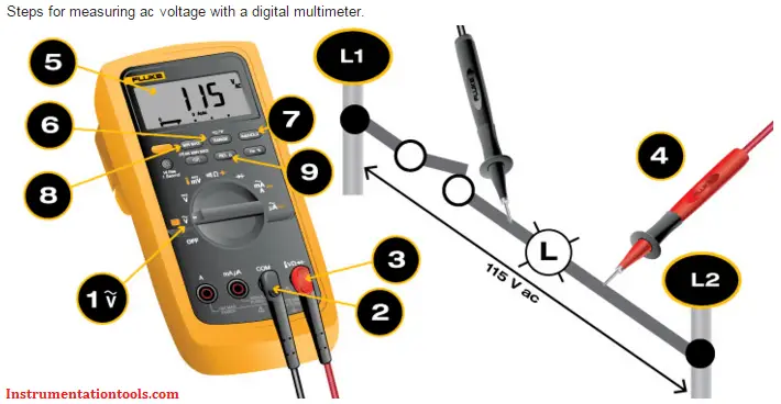
1. Turn the dial to ṽ. Some digital multimeters (DMMs) also include m ṽ . If voltage in the circuit is unknown, set the range to the highest voltage setting and set the dial on ṽ.

Note: Most multimeters power up in Autorange mode. This automatically selects a measurement range based on voltage present.

2. First insert the black lead into the COM jack.

3. Next insert the red lead into the VΩ jack. When finished, remove the leads in reverse order: red first, then black.

4. Connect the test leads to the circuit: black lead first, red second.

Note: ac voltage does not have polarity.

Caution: Do not let fingers touch the lead tips. Do not allow the tips to contact one another.

5. Read the measurement in the display. When finished, remove the red lead first, black second.

Other useful functions when measuring ac voltage

6. Press the RANGE button to select a specific fixed measurement range.

7. Press the HOLD button to capture a stable measurement. It can be viewed after the measurement is complete.

8. Press the MIN/MAX button to capture the lowest and highest measurement. The DMM beeps each time a new reading is recorded.

9. Press the relative (REL) button to set the multimeter to a specific reference value. Measurements above and below the reference value are displayed.

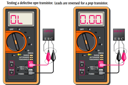
Note: Avoid this common and serious mistake: inserting test leads into incorrect input jacks. Doing so can lead to a dangerous arc flash. If measuring ac voltage, be certain to insert the red lead into the input jack marked V, not A. The display should show the ṽ symbol. Placing test leads in A or MA inputs and then measuring voltage will create a short in the measurement circuit.

Analysis of ac voltage measurements

  • In general, all ac voltage sources vary from fluctuation in ac voltage over power distribution systems.
  • When different from an expected measurement, voltage is more likely to be lower than normal.
  • Generally speaking, voltage measured in ac power systems should be within -10% and +5%.
  • Voltage measurements taken at various points in a system vary. Refer to the chart below.
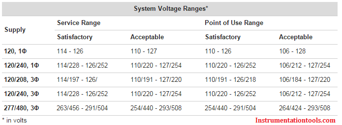
Multimeter Supply Voltage Ranges

Source : Fluke

Also Read: Measure Capacitance using Multimeter

Don't Miss Our Updates
Be the first to get exclusive content straight to your email.
We promise not to spam you. You can unsubscribe at any time.
Invalid email address
You've successfully subscribed !

Continue Reading

What is a Fuse ?
Top 555 Timer Projects for Engineering Students
Things to Know When Measuring Current
Power Supply Circuit Fault Analysis
Difference between Intrinsic and Extrinsic Semiconductors
How are Silicon Chips Disposed?
Share This Article
Facebook Whatsapp Whatsapp LinkedIn Copy Link
Share
1 Comment
  • SANJAY says:
    March 10, 2016 at 3:00 am

    I want to join you group Pl give me advise me I am working with ONGC as an AEE (INSTRUMENTATION) at CWS VADODAR.

    Reply

Leave a Reply Cancel reply

Your email address will not be published. Required fields are marked *

Stay Connected

128.3kFollowersLike
69.1kFollowersFollow
208kSubscribersSubscribe
38kFollowersFollow

Categories

Explore More

How to Test Diodes Using Multimeter
Difference Between Common Cathode and Common Anode 7 Segment LED Display?
Definition of Accuracy, Precision, Resolution, Range
What is a Non-Linear Device? Example – Advantages
What is PCB Corrosion? Electronic Boards Corrosion Prevention
How a Transistor Switch Works
How to Use SMD Components in Electronic Circuits?
IEC labelling for Resistors Color Code

Keep Learning

Motor contactors

What is Contactor ?

What is Oscilloscope

What is Cathode Ray oscilloscope ?

How to Test a Battery using Multimeter

How to Test a Battery using a Multimeter?

100 Electronics and Electrical Projects for Engineering Students

100 Electronics and Electrical Projects for Engineering Students

Difference Between LED and LCD

Difference Between LED and LCD

How to Identify the Transistor Terminals

Measure Duty Cycle using Multimeter

How to Measure Duty Cycle using Multimeter

Tank car bonding at siding

Electrical Static Grounding Techniques

Learn More

Parts of Safety PLC

SIS Software Simulation – Safety Instrumented System

Suspended Particulate Matter

Basics of Suspended Particulate Matter (SPM) Analyzers

Compare Serial and Parallel Communication

Difference Between Serial and Parallel Communication

Process variable to 4-20mA Conversion

Formula to Calculate 4-20 mA from Process Variable

Valve Sequencing

Complementary Control Valve Sequence

Metering components to measure flow of Natural gas

Is it Easy to Measure Natural Gas Flow and Volume?

GATE Instrumentation Questions and Answers

GATE Instrumentation Questions and Answers

Laser Cutting Precision and Accuracy

Benefits of Steel Laser Cutting

Follow US
All rights reserved. Reproduction in whole or in part without written permission is prohibited.
Welcome Back!

Sign in to your account

Username or Email Address
Password

Lost your password?