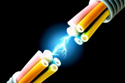
Electrical cables will not always function like they are designed for perfect use. Some reason or the other will cause the cable to break down. If the fault is not detected on time, then it can lead to serious damage.
And especially if the cable is some high-voltage distribution wire, then the fault analysis and detection becomes more critical, failing which cause untoward incidents.
How to Locate Faults in Cables?
An electrical cable is designed to carry electrical current safely to a destination. But, even if the cable is designed for a long lifetime, some causes occur to fail it.
Even if the technician to determine the fault is highly qualified, it takes a certain amount of time to unearth and find it. So, it is necessary to understand some general reasons for how a fault can occur.

Causes of Cable Faults
Let us have a look at some causes of cable faults:
- The cable is protected by an outer tough layer called a sheath. If the sheath tears or breaks, then it exposes a risk to the inner conductor with moisture, pollution, dust, or other impurities.
- If the current in the cable increases beyond its limit, then too the cable gets damaged after a period of time due to overcurrent which causes thermal breakdown (overheating).
- If the cable accidentally touches the ground or earth point, then it can create earth leakage or even short-circuit. This damages the cable due to overheating.
- When the insulation of the cable breaks down, it causes the inner conductor current to start flowing outside and spread the electric field in unwanted areas. This creates electrical stress and damages the cable after a period of time.
What are the methods of locating cable faults?
The general sequence for locating cable faults works in a four-step sequence:
- first identifying the type of fault (analysis),
- then tracing the nearby location (location),
- then tracing the exact location (pinpointing), and
- identifying the cable.
A] Fault analysis
Insulation resistance:
The insulation Resistance method is also known as the Meg test (Megger test) and is used to determine the resistance of fault and to identify which type of voltage to apply for further troubleshooting. Generally, it is classified into three types – low, medium, and high.
Depending on the insulation material and the value of resistance, we can then decide which voltage to apply to the cable for further analysis. Both the cable ends are stripped and a Megger is connected to them.
A voltage is applied due to this and the resistance is measured in MOhms. If it passes the required value, then you determine what voltage needs to be passed through the cable for further analysis.
Breakdown detection:
If the fault is highly resistive, then a high voltage must be applied to it until a point where the breakdown of the cable occurs. The breakdown detection method determines the minimum voltage which can be applied in the fault location test, for identifying the fault location further.
Cable sheath testing:
It determines the integrity of the cable sheath. This is an important test as the sheath is the main outer layer for cable protection.
Depending on the sheath size, the voltage is applied to the cable sheath and it checks whether it has any effect on it. If any breakdown occurs, then that voltage is recorded, and said that beyond this, the sheath will break down.
B] Fault location
Thumping a cable:
Thumping is a method of fault location. This is probably the oldest and most traditional method of cable fault detection. In this technique, a surge wave generator (thumper) which generates a very high voltage is fed to the cable. If the cable is proper, then this voltage will reach the desired end safely.
But, if there is any breakdown in insulation, then it will create an electric stress in that area and cause the electric field to spread outside. Due to this, you can hear a loud sound in that area, or in the other way, this return current will come back to the surge generator and get detected through this.
This testing is mostly done underground with the cable, as such a high voltage can cause accidents if touched or exposed. Once the sound is heard or the point of breakdown is detected, the operator travels to that point and rectifies that area to find the exact point.
Time domain reflectometry:
TDR is a method of fault location. A device called TDR or time domain reflectometry is used which has a set of transmitters and receivers. It sends a low voltage high-frequency pulse of a short duration to the cable.
This echo pulse then travels throughout the cable length. If any obstacle comes in between, this pulse travels back to the device. Depending on the type of obstacle (like an open circuit, short circuit, splice, Z mismatch, or loose contact), the type of waveform display varies and the user identifies what type of fault it is.
The time when the pulse was disturbed is plotted on the graphical display and using this time, the near distance from the start to the fault end can be calculated easily. This results in more accurate fault detection.
Arc reflection:
This method is an extension of the TDR method. TDR works fine for low-resistive faults or low voltage faults, but not for medium-resistive or high-resistive faults. This is because the TDR pulse is low voltage and will not be able to detect it.
So, the arc reflection method is a combination of TDR and thumping, which sends a high voltage pulse across the cable for detecting fault location.
C] Exact Fault Location (Pinpoint)
Active tracing:
The active tracking method uses an audio frequency generator for fault detection. Basically, the concept is that electromagnetic fields exist around a conducting cable and if there is any fault around it, then the field will not be proper.
So, to detect it, this generator will give high-frequency signals to the cable. This method is best suitable when you cannot access the cable or when the cable is difficult to disconnect. So, to connect the generator, the three methods used are – galvanic, inductive using a clip, and inductive using an antenna.
Galvanic connection works by directly connecting the cable of the generator to the phase of the cable. But, it works only when the power is disconnected from the cable.
Inductive connection works by surrounding the cable of the generator around the cable to be detected. Due to this, you can work with live wires here. It is similar to a current transducer which is wound around a cable, for current measurement. Without touching it, you get the values.
So, irrespective of any method, the concept works based on electromagnetic signals fed to the cable. At a certain set frequency, the operator stands around the location where the nearby location was detected earlier. Then, using this generator, signals are sent to the cable and received at the other end of the surface.
When the fault location is found, the signal distorts here and the generator will show the corresponding waveform. As they are time stamped and also as you are near the location, you get to know the exact location through calculations with respect to time and frequency.
Acoustic tracing:
As the name suggests, the method involves detecting the fault by hearing sound. If you remember our first post, we used a method called thumping, where high-voltage spikes were sent. The same method works here, but at the location we found first.
When you are near to the location, the high-voltage spikes are sent to the cable. If there is a fault, a loud sound will be heard as the electric field has now become open around the fault area. The operator hears it through a microphone, headphone, or receiver. If the sound heard is loud, it means you are very near to the exact fault location.
Step voltage method:
The acoustic method cannot work for short circuits, because electric fields come out only through open circuits, thus causing the inability to produce sound. In this method, voltage spikes are sent to the cable and a device for measuring voltage gradient or change is used, instead of headphones.
When there is a short-circuit fault, the resistance offered is minimal. Due to this, the voltage pulses will go to the surrounding ground, and at the ground, earth probes are placed. When you place your voltage testing device at the probes, you will observe a voltage and this voltage increases as you go near the fault.
At the exact fault location, the voltage will cross such a high value that it will inverse in polarity. This is the fault location that you require.
D] Cable Identification
This is the last step for finding the fault location. The methods discussed above work best for a single cable. The problem occurs when there are multiple cables. The methods that we saw earlier will give the same result in finding you the exact pinpoint location. But, once you reach the location and find multiple cables, then how to find the real culprit?
In this case, a device called cable identifier is used for detecting the exact cable having a fault. The same transmission-receival concept works here too. The signal is sent to a single cable and due to the cables being interconnected through the same ground, some portion of the current will return to the ground.
A detector is used at the receiver end. Out of the cables which have not received a signal, the faulty cable will show a higher ratio of amplitude, phase, and frequency due to the fault. This will show you the faulty cable in that case.
Read Next:
- De-energize to Safe Loop Basic Philosophy
- Top 300 Electrical Circuits Questions Answers
- Free Electrical Circuit Simulators Download
- Instrumentation Cables Testing Standards
- Miniature Circuit Breakers Questions Answers
