Inst ToolsInst ToolsInst Tools
  • Courses
  • Automation
    • PLC
    • Control System
    • Safety System
    • Communication
    • Fire & Gas System
  • Instrumentation
    • Design
    • Pressure
    • Temperature
    • Flow
    • Level
    • Vibration
    • Analyzer
    • Control Valve
    • Switch
    • Calibration
    • Erection & Commissioning
  • Interview
    • Instrumentation
    • Electrical
    • Electronics
    • Practical
  • Q&A
    • Instrumentation
    • Control System
    • Electrical
    • Electronics
    • Analog Electronics
    • Digital Electronics
    • Power Electronics
    • Microprocessor
  • Request
Search
  • Books
  • Software
  • Projects
  • Process
  • Tools
  • Basics
  • Formula
  • Power Plant
  • Root Cause Analysis
  • Electrical Basics
  • Animation
  • Standards
  • 4-20 mA Course
  • Siemens PLC Course
Reading: How to Create DFB in Schneider PLC? – Derived Function Block
Share
Font ResizerAa
Inst ToolsInst Tools
Font ResizerAa
  • Courses
  • Design
  • PLC
  • Interview
  • Control System
Search
  • Courses
  • Automation
    • PLC
    • Control System
    • Safety System
    • Communication
    • Fire & Gas System
  • Instrumentation
    • Design
    • Pressure
    • Temperature
    • Flow
    • Level
    • Vibration
    • Analyzer
    • Control Valve
    • Switch
    • Calibration
    • Erection & Commissioning
  • Interview
    • Instrumentation
    • Electrical
    • Electronics
    • Practical
  • Q&A
    • Instrumentation
    • Control System
    • Electrical
    • Electronics
    • Analog Electronics
    • Digital Electronics
    • Power Electronics
    • Microprocessor
  • Request
Follow US
All rights reserved. Reproduction in whole or in part without written permission is prohibited.
Inst Tools > Blog > PLC Tutorials > How to Create DFB in Schneider PLC? – Derived Function Block

How to Create DFB in Schneider PLC? – Derived Function Block

In this article, we will learn how to create user derived function block (DFB) in machine expert, unity pro schneider PLC.

Last updated: September 28, 2022 4:10 pm
Viral Nagda
PLC Tutorials
No Comments
Share
6 Min Read
SHARE

In this post, we will learn how to create DFB in Schneider PLC.

Contents
Machine Expert BasicMachine ExpertUnity Pro

Derived Function Block (DFB) is a very important tool in reducing the working time of a programmer for creating a repetitive type of logic. Basically, it is a function block created by the programmer; similar to the function blocks (libraries) which are predefined in the PLC programming software.

In this post, we will learn to create DFB’s in Schneider PLC. Here, we will see 3 types of programming software in Schneider PLC – Machine Expert Basic, Machine Expert and Control Expert.

Machine Expert Basic

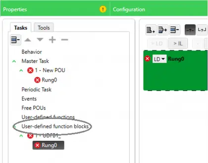
Right-click User-defined function blocks in the Tasks window as shown in figure. Then, you will get the option to add a DFB.

Add it and a by default DFB name of UDFB1_ will be created.

You can then rename it according to your needs. As you go on adding DFB, the number will be incremented as 2_, 3_, 4_ etc.

Derived Function Block (DFB) in PLC

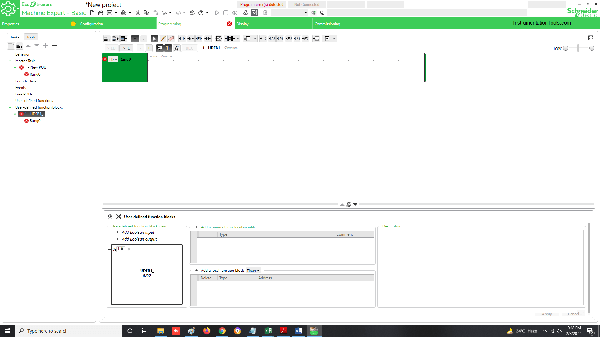
After DFB has been added, you will see the following window in the bottom of the software layout.

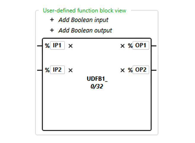
As a DFB has inputs and outputs similar to function block library, you have to add inputs and outputs to the DFB according to your requirement.

DFB in Schneider PLC

In the below image, I have added 2 inputs and 2 outputs to the DFB by clicking Add Boolean input and Add Boolean output button.

You can double-click the rectangle as an input or output is added and rename it.

In the below example, I have renamed it as IP1, IP2, OP1 and OP2.

Function Block View in PLC

Now, just an input and output is not enough to write a logic inside the function block.

You will need other local or in-out variables and other in-built software libraries to build the logic.

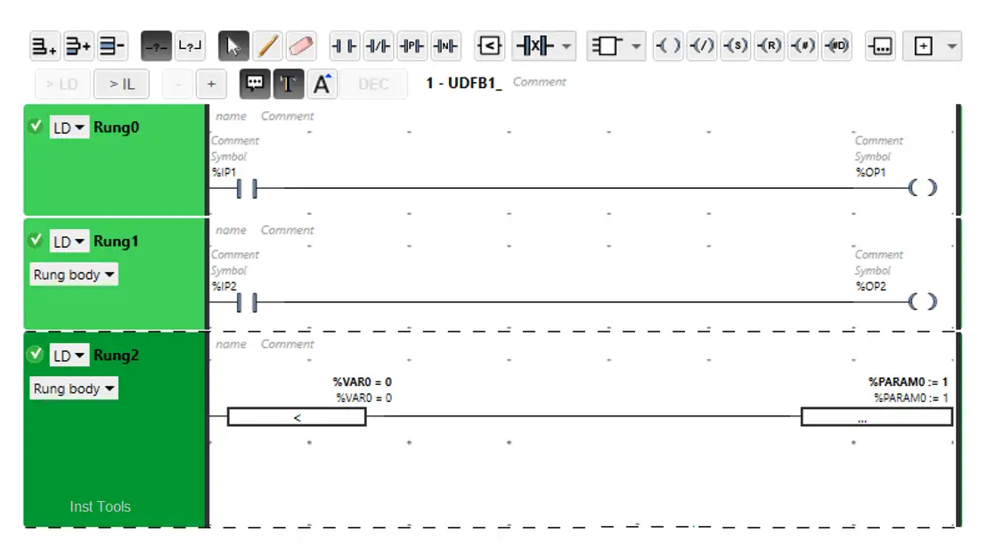
Refer the below image. I have added a parameter named PARAM0 and a local variable named VAR0.

logic inside the function block

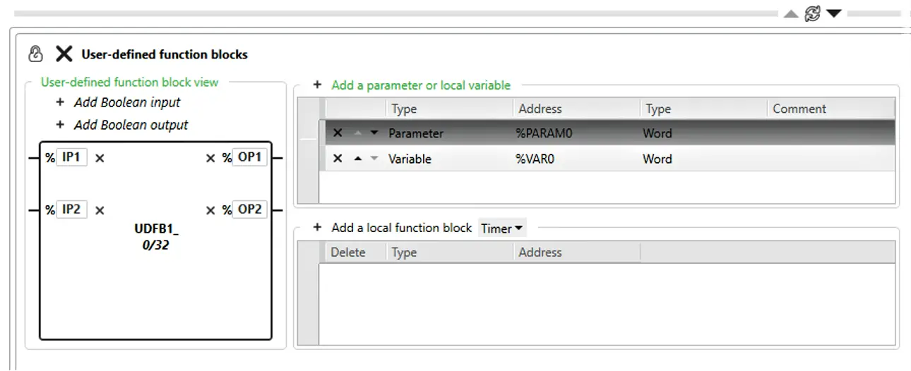
Below image shows the logic written for all the variables created. You can use PARAM0 outside the DFB.

VAR0 can be used locally inside the DFB only.

PLC logic written for all the variables

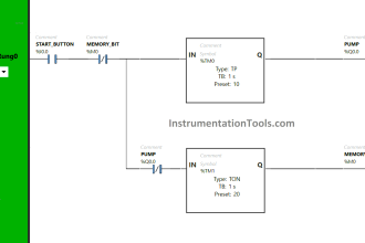
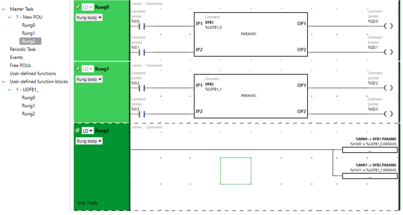
Refer the below image for DFB’s used in the program. I have used two instances of the DFB in the logic – DFB1 and DFB2.

As you can see, if I had not used DFB, then I would have to write a total of 6 rungs (3 rungs of the DFB as mentioned above earlier * 2) in the program. But here, due to use of DFB, rungs are saved.

You just have to link the variables to the inputs and outputs. All the DFB’s work simultaneously with the same logic inside.

Also, I have used PARAM0 variable outside in the logic as shown; to write it’s value to a memory word.

How to Create DFB in Schneider PLC

You can use a DFB in the program by clicking the following option as shown below.

DFB in PLC

Machine Expert

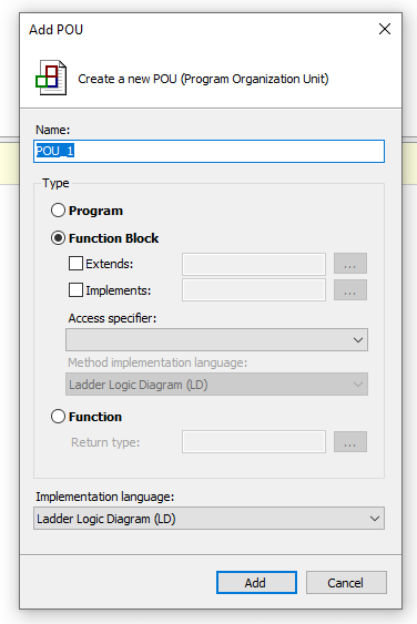
For creating a DFB, right-click on the application tab and click Add POU. You will get the following window as shown.

Choose Function Block and select the corresponding programming language you want to develop the logic in.

Create a New POU in PLC

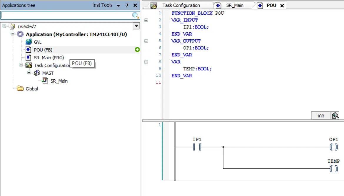
Now, refer to the below image. You can see that I have added one input named IP1 in the input variable list; and one output named OP1 in the output variable list.

A local variable named TEMP has been defined.

Unity Pro XL in DFB (Derived Function Block)

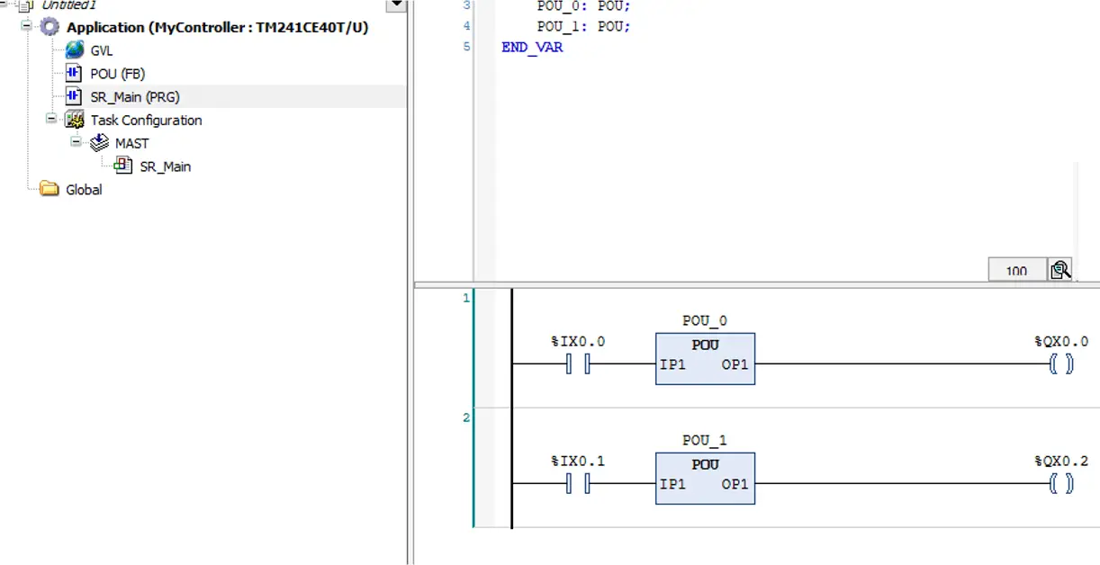
Now, in the main program where you want to use the DFB, insert a box and assign the DFB defined earlier.

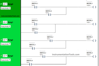
In the below image, I have created two instances of the DFB – POU_0 and POU_1.

Schneider Unity Pro - DFB

Unity Pro

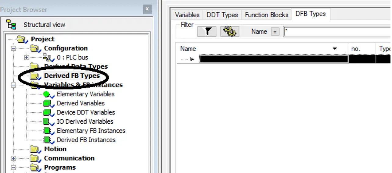
Refer to the below image. You can see the option of Derived FB Types.

Double click it and a window will open in the right side as shown.

Derived Function Block Unity Pro

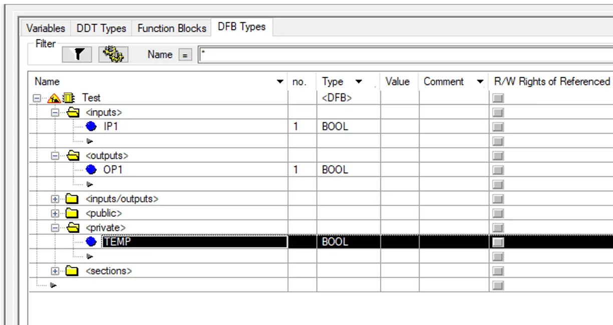
In the below image, you can see that I have added an input named IP1 and an output named OP1 in the variable list.

Also, a local variable named Temp has been added.

How to Create a Unity Pro Derived Function Block

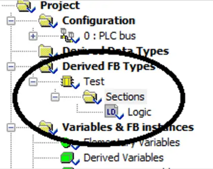
In the below image, right click the Sections and you will get an option to add the logic. In the logic, create your logic part and add it’s instance in the main program then as discussed in earlier sections.

It is the same procedure.

add the logic in PLC

In this way, we saw how to create DFB’s in Schneider PLC.

If you liked this article, then please subscribe to our YouTube Channel for Electrical, Electronics, Instrumentation, PLC, and SCADA video tutorials.

You can also follow us on Facebook and Twitter to receive daily updates.

Read Next:

  • Nameplate of a Motor
  • Solenoid-controlled Valve
  • MODBUS ASCII Communication
  • DCS Alarm Summary Dashboard
  • AC Fundamentals Questions
Don't Miss Our Updates
Be the first to get exclusive content straight to your email.
We promise not to spam you. You can unsubscribe at any time.
Invalid email address
You've successfully subscribed !

Continue Reading

Software Troubleshooting Errors and Faults in Siemens PLC
Global Acknowledgment Instruction in Safety PLC
Siemens PLC Interview Questions and Answers
PLC Batch System for 4 Tanks Mixing using CX-Programmer
DeMorgan’s Theorems using Ladder Diagram
PLC Program for Solenoid, Pilot Lamp, and Switch with Alarm
Share This Article
Facebook Whatsapp Whatsapp LinkedIn Copy Link
Share
Leave a Comment

Leave a Reply Cancel reply

Your email address will not be published. Required fields are marked *

Stay Connected

128.3kFollowersLike
69.1kFollowersFollow
210kSubscribersSubscribe
38kFollowersFollow

Categories

Explore More

Vijeo Designer software – Import and Export
Introduction to Functional Block Diagram in Studio 5000
Basics of Motion Controllers
What is a Watchdog Timer in PLC?
PLC Automatic Control of Two Outputs with one Input
FOR DO Statement in SCL Language
#8 PLC Best Practices – Validate HMI Input Variables at PLC Level
Automatic Highway Lights Program using RTC in Omron PLC

Keep Learning

Omron PLC for Product Painting with Integrated Weighing System

Omron PLC for Product Painting with Integrated Weighing System

100 PLC Quiz Questions

100 PLC Quiz Questions : True or False

PLC Program to Operate Stamping of Parts

PLC Application for Stamping Operation – Example Programming

PLC Program for Automatic Door Control System

PLC Automatic Door Control System – Programming Example

Automatic Lamp Control in Storage Facility

PLC Program for Automatic Lamp Control in Storage Facility

Learn PLC Programming

Basics of Ladder Diagram in PLC Programming

Free Siemens PLC Training Course

Free Siemens PLC Training Course

Why is 24 Volts Commonly used in PLC Systems?

Why is 24 Volts Commonly used in PLC Systems?

Learn More

Comparison of Level Meters - Level Measurement Instruments

Comparison of Level Meters – Level Measurement Instruments

Intrinsic Safety Zones

Intrinsic Safety Protection ia and ib

Construction of strain gauge Load cell

Strain Gauge Load Cell

Acceptable Earth Resistance Values

Acceptable Earth Resistance Values

Interview Questions for Instrumentation Engineer Freshers

Interview Questions for Instrumentation Engineer Freshers

Maintenance Override Switch (MOS)

What is Maintenance Override Switch (MOS) ?

Manual Call Point Testing Procedure

Manual Call Point Testing Procedure

Commissioning Checklist for Industrial Automation System

Commissioning Checklists for Industrial Automation Systems

Menu

  • About
  • Privacy Policy
  • Copyright

Quick Links

  • Learn PLC
  • Helping Hand
  • Part Time Job

YouTube Subscribe

Follow US
All rights reserved. Reproduction in whole or in part without written permission is prohibited.
Welcome Back!

Sign in to your account

Username or Email Address
Password

Lost your password?