The following instructions describe how to configure a 2 wire Radar smart transmitter with HART communicator using an Emerson 475 Field Communicator. The 475 Field Communicator used for this article contained system software version 3.7. In this article, the Emerson 475 Field Communicator will be referred to as the “475 Communicator”. For additional information on the operation of the 475 Communicator please refer to the user manual.
Menus in the 475 Communicator are displayed as a numbered list. In order to activate a menu item, you must use the keyboard and enter the number associated with the menu item. For example to select the menu item “1 Device setup“, you must press the number 1 on the keyboard. Tapping on the screen will only highlight the menu item.
Configure a Smart Transmitter
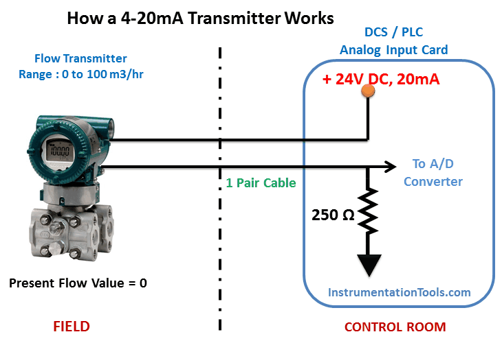
1. Connect power to your HART enabled Radar transmitter. Figure 1 shows a wiring diagram, the required load resistor, and loop voltage.

Note: When you connect the radar transmitter to the PLC or DCS system then the 250-ohm resistor already included at the system side, so you can directly connect HART communicator terminals across transmitter terminals. The additional 250-ohms resistor required only when we use power supply units to power the transmitter in the calibration labs.
2. Power on the 475 Communicator by pressing and holding the power key until the green light on the power key blinks.
3. From the main menu tap the HART icon. The HART icon can be seen in the upper left corner of Figure 2.

Figure 2 shows the main screen of the 475 Communicator.
4. The 475 Communicator will request the manufactures code and model number from the Radar unit. The information is used to load a device descriptor if one is installed on the Communicator. If a device descriptor is not installed the 475 Communicator will use the HART universal and common commands to program the Radar.
Figure 3 shows the message displayed when a device descriptor is not found.

Figure 3 shows the 475 Communicator screen when a device descriptor file is not found.
5. Tap the “YES” button on the bottom left side of the screen (Figure 3) to proceed. The next screen shown on the 475 Communicator is referred to as the “HOME” screen. Figure 4 shows the home screen.
The home screen displays the Radar calibration values, the target distance and loop current. The primary variable (PV) in Figure 4 is the target distance at 3.442 feet. The PV Loop current is 19.507mA. The PV lower range value (LRV), and upper range value (URV) represent the Radar range calibration values.

Figure 4 shows the home screen.
6. The home screen communicates continuously with the Radar providing up-to-date measurement and loop information.
An alternative screen is shown in Figure 5 (far right) can be displayed by following the menu selection shown.

Figure 5 show the menu selections required to view the Primary Variables screen.
Changing Calibration Values
The 475 Communicator provides multiple screens and menus for calibrating the Radar. The Radar range can be calibrated from the home screen using menu items “4 PV LRV” and ”5 PV URV” or by entering “1 Device setup“.
Changing the range from the home screen is quick but has limited options. The device setup menus provide access to the range and other programmable features. Both methods will be described in the text to follow.
The appendices at the end of this article contain quick reference diagrams for each of the calibration changes described in this section.
Changing Calibration Values from the Home Screen
7. Figure 6 (left) shows the Home screen. The Radar range can be changed by selecting the menu item “4 PV LRV” or ”5 PV URV”.
Selecting either menu item will cause the Communicator to display the range calibration screen as shown in Figure 6 (right).

Figure 6 selecting menu item 4 or 5 from the home screen (left) causes the screen to change to the range calibration screen (right).
8. Selecting menu item “1 PV URV” from the range calibration screen (Figure 6 right) will change the display to an edit screen. The edit screen allows a distance to be entered for the URV as shown in Figure 7.

Figure 7 shows the URV and LRV edit screens.
9. Be aware of the “unit of measure” shown next to the current URV and LRV (ft = feet) when entering your desired distance. When you have entered the distance tap the “ENTER” button.
The change will not take effect until they are sent to the Radar. To send the changes to the Radar tap the “SEND” button in Figure 8.

Figure 8 shows a warning screen that appears when calibration values are changed. The change must be sent to the Radar using the SEND button before they take effect.
Using Device Setup to Change Calibration Values
10. Figure 9 (left) shows the Home screen. Range calibration and other programmable values can be accessed by selecting “1 Device setup”. The Device setup screen is shown in Figure 9 (right).

Figure 9 after selecting menu 1 from the home screen (left) the “Device Setup” screen (right) will be displayed.
11. The “Basic setup” screen shown in Figure 10 (right) provides menus to change common calibration values.
To display the Basic setup screen select “3 Basic setup” from the device setup screen.

Figure 10 shows the “Device setup” menus (left) and the “Basic setup” menus screen (right).
12. The basic setup screen provides menus to change HART descriptive tags, unit of measure, range values and PV Damp.
Device Setup → Basic Setup → Range Values
13. To change the Radar range distance values from the Basic setup screen select menu “4 Range values”. The “Range values” screen seen in Figure 11 (right) will be displayed.
The range values screen shows the range calibration values (menu items “1” and “2”) and the upper and lower sensor limits (menu items ”4” and ”5”). As shown in Figure 11, the Radar has a limit of 100 feet.

Figure 11 shows the menu item selection to get to the range values screen.
14. Selecting menu “1 PV URV” or “2 PV LRV” from the “Range values” screen in Figure 11 will bring up the appropriate URV or LRV edit screen as shown in Figure 7.
Device Setup → Basic Setup → Unit of Measure
15. The Radar default unit of measure is feet. The unit of measure can be change by selecting menu “3 PV Units” from the Basic setup as shown in Figure 12.
The Radar supports feet (ft), inches (in), meters (m) and centimeters (cm). Scroll up or down to find the desired unit of measure. Tap on the unit of measure and then tap ENTER.

Figure 12 shows the unit of measure screen. The unit of measure can be changed to feet (ft), inches (in), meters (m) or centimeters (cm).
Device Setup → Basic Setup → Damping
16. Process variable measurement is averaged using a damping factor known as PV Damp. Radar units are shipped with a PV Damp default value of 5. The PV Damp value can be changed from the Basic setup screen menu ”7”.
Figure 13 shows the PV Damp edit screen. It should be noted that increasing PV Damp will slow down the Radar response

Figure 13 shows the PV Damp edit screen
Device Setup → Diag/Service → 4mA and 20mA Calibration
17. The 4mA and 20mA distance values can be manually keyed in using the URV and LRV edit screens shown in Figure 7. To manually enter a distance value, refer to steps 2-1, 2-7 or 2-12. An alternative method is to set the 4mA or 20mA distance to the current distance being measure by the Radar.
For example, the current measured distance could represent the top or bottom of a tank or the desired full or empty point. Setting the 4/20mA distance can be done using the Calibration menu found in the “Diag/Service” screen.
Figure 14 shows the menu selection to get to the “Diag/Service” Screen.

Figure 14 shows the menu path to Diag/Service screen.
18. From the Diag/Service (Figure 15 left) select menu “3 Calibration” to display the Calibration screen. From the Calibration screen (Figure 15 right) you have the choice of manually entering distance values or using the measured distance.
To manually enter the distance, select menu “2 Enter values”. You will be prompted to select 4mA or 20mA (Figure 16) before the edit screen is displayed.

Figure 15 shows the Calibration menu (right)

Figure 16 shows the choices available when setting the 4mA and 20mA distance.
19. To set the 4mA or 20mA value to the current distance select menu ”1 Apply values” from the Calibration screen (Figure 15 right). Select the value you want to set (Figure 17 left).
In the following example, the 4mA distance value will be set. The process for setting the 20mA distance is the same. Figure 17 (right) shows the resulting screen when the 4mA value is selected. Tapping “OK” will show the screen in Figure 18.

Figure 17 shows the LRV edit screen.
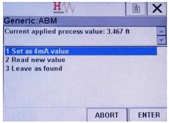
Figure 18 shows the URV edit screen.
20. The measured distance is displayed in the top section of Figure 18. To use this distance select menu “1 Set as 4mA value”.
If the distance is incorrect adjust the target or wait for the target distance to reach the desired value and then select menu “2 Read new value”. Menu ”2” will read the new distance from the Radar. Note that setting the 4mA distance will cause the loop current to change to 4mA.
Warnings Screens in HART Communicator
21. Changing calibration values in the Radar may affect the loop current. Warning screens like those shown in Figure 19 may appear. Tap the “OK” to proceed with the calibration change.
After a calibration value has been changed on the 475 Communicator the changes must be sent to the Radar unit to take effect. Figure 20 shows the warning screen displayed after the change.
Tapping “SEND” will write the new value in the Radar. Tapping “ABORT” will cancel the write operation.

Figure 19 shows 2 examples of warning screens.

Figure 20 shows a warning screen that appears when calibration values are changed. The change must be sent to the Radar using the SEND button before they take effect.
Non-zero Status Screens
22. When a calibration value is changed in the Radar a configuration change flag bit is set in the resulting HART status code. The 475 Communicator will detect the flag and display a non-zero status code screen as shown in Figure 21.
The screen is a confirmation that the Radar configuration has changed. The flag will remain set in all status codes sent to the 475 Communicator until the 475 Communicator tells the Radar to clear the flag.
Non-zero status codes can be ignored by tapping “YES”.

Figure 21 shows Non-zero Status Screens
Reviewing Calibration Settings
23. The 475 Communicator provides a set of menus to review the Radar calibration settings. From the “Device setup” screen select menu “5 Review” (Figure 22).

Figure 22 shows the Review menu item highlighted.
24. The “Review” screen, Figure 23 provides a scrollable list of calibration values.
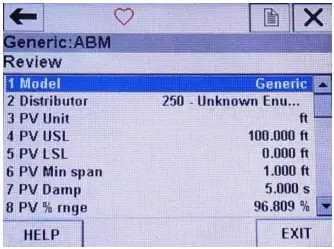
Figure 23 shows the Review screen.
HART Communicator Shortcuts
Short Cut to Range Values

Figure 24 shows the menu selections to change the URV and LRV.
Menu Path to Common Calibration Values

Figure 25 shows the menu path to commonly used calibration values.
Menu Path to 4mA and 20mA Calibration

Figure 26 shows the menu path to 4mA and 20mA calibration. The lower half of the diagram illustrates setting the 4mA value to the measured distance.
Source: AMB Sensor


Fantastic
Really, informative and practical knowledge.
can anyone guide me that during 4-20mA calibration, how will we give distance value to radar transmitter. As it is not in process, it is in calibration lab.
How we will assure that the radar transmitter is reading 1ft and it is reading 80ft for zero and span respectively
As in PT, we use calibration pump to apply pressure and set 4mA and 20mA accordingly.
Thanks for your great concern for this tutorial
Great and very good knowledge thanks for this site.