Inst ToolsInst ToolsInst Tools
  • Courses
  • Automation
    • PLC
    • Control System
    • Safety System
    • Communication
    • Fire & Gas System
  • Instrumentation
    • Design
    • Pressure
    • Temperature
    • Flow
    • Level
    • Vibration
    • Analyzer
    • Control Valve
    • Switch
    • Calibration
    • Erection & Commissioning
  • Interview
    • Instrumentation
    • Electrical
    • Electronics
    • Practical
  • Q&A
    • Instrumentation
    • Control System
    • Electrical
    • Electronics
    • Analog Electronics
    • Digital Electronics
    • Power Electronics
    • Microprocessor
  • Request
Search
  • Books
  • Software
  • Projects
  • Process
  • Tools
  • Basics
  • Formula
  • Power Plant
  • Root Cause Analysis
  • Electrical Basics
  • Animation
  • Standards
  • 4-20 mA Course
  • Siemens PLC Course
Reading: How Overload Heaters used to Automatically Shut the Motor OFF ?
Share
Font ResizerAa
Inst ToolsInst Tools
Font ResizerAa
  • Courses
  • Design
  • PLC
  • Interview
  • Control System
Search
  • Courses
  • Automation
    • PLC
    • Control System
    • Safety System
    • Communication
    • Fire & Gas System
  • Instrumentation
    • Design
    • Pressure
    • Temperature
    • Flow
    • Level
    • Vibration
    • Analyzer
    • Control Valve
    • Switch
    • Calibration
    • Erection & Commissioning
  • Interview
    • Instrumentation
    • Electrical
    • Electronics
    • Practical
  • Q&A
    • Instrumentation
    • Control System
    • Electrical
    • Electronics
    • Analog Electronics
    • Digital Electronics
    • Power Electronics
    • Microprocessor
  • Request
Follow US
All rights reserved. Reproduction in whole or in part without written permission is prohibited.
Inst Tools > Blog > Practical Questions > How Overload Heaters used to Automatically Shut the Motor OFF ?

How Overload Heaters used to Automatically Shut the Motor OFF ?

Last updated: August 9, 2019 12:17 pm
Editorial Staff
Practical Questions
No Comments
Share
3 Min Read
SHARE

How Overload Heaters used to Automatically Shut the Motor OFF & Prevent Damage ?

Some common components of three-phase motor control circuits are shown here in the following illustrations.

These include fuses, a contactor, and an overload assembly:

three-phase motor control circuits

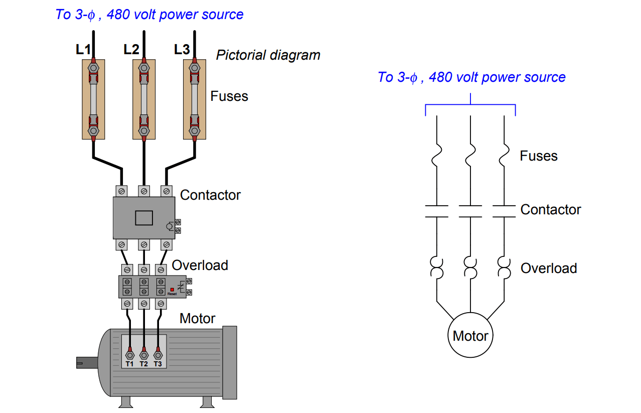
Fuses protect the power wiring from gross overcurrent conditions such as what might happen if there were an accidental phase-to-phase short-circuit inside the motor.

The contactor is nothing more than a big relay with three normally-open contacts to send power to the motor, serving to start and stop the motor on command with a 120 volt signal to its coil.

The overload block, however, is a little more mysterious. Its three “heater” elements (looking like backto-back “question mark” symbols in the schematic diagram) carry the motor’s current from the contactor to the motor terminals.

These resistive heaters are designed to become warm under normal operating conditions, just as the motor itself will become slightly warm under normal conditions from resistive power losses in its windings.

If the motor ever becomes too warm as a result of overloading (slight overcurrent), the overload heaters (which will also be too warm due to the overcurrent) will trigger a small thermally-operated switch contact to spring open.

Connection terminals for this small switch contact may be seen on the right-hand side of the overload block in the pictorial diagram.

Explain how the overload heaters may be used to automatically shut the motor off and prevent damage ?

Answer :

If you thought the overload heaters would open up like fuses in the event of an overload condition (becoming too warm) to directly interrupt motor current, you have made a very common error! Don’t feel bad, though – I won’t tell anyone.

In order for the overload assembly to automatically shut down the motor, its small switch must be connected to something. I’ll let you figure out what that something is!

Share Your Answer / Comments

Credits : by Tony R. Kuphaldt – under CC BY 1.0

Don't Miss Our Updates
Be the first to get exclusive content straight to your email.
We promise not to spam you. You can unsubscribe at any time.
Invalid email address
You've successfully subscribed !

Continue Reading

Programmable Logic Controller (PLC) Questions and Answers – 2
Calculate the appropriate millivoltage values of a Thermocouple
Identify Two Pressure Switches Logic
Identify Problem with Oily Water Filter Instrumentation
Which Instrument is at Fault in this System?
Calculate Differential Pressure Sensed by Level Transmitter
Share This Article
Facebook Whatsapp Whatsapp LinkedIn Copy Link
Share
Leave a Comment

Leave a Reply Cancel reply

Your email address will not be published. Required fields are marked *

Stay Connected

128.3kFollowersLike
69.1kFollowersFollow
210kSubscribersSubscribe
38kFollowersFollow

Categories

Explore More

Troubleshooting PLC Permissive Inputs
Practical Process Control System Questions & Answers – 11
Programmable Logic Controller (PLC) Questions and Answers – 3
Pneumatic Level Transmitter Calibration Table
Paint Mixing System
Process Control Loop Testing
Is it Possible to Measure Liquid-Liquid Level Interface using Float?
Determine Calibration Range of Pneumatic Pressure Transmitter

Keep Learning

A span error with wrong slope

Determine the Instrument Calibration Error

liquid flow control system

Practical Process Control System Questions & Answers – 7

Motor ladder Logic

Draw a ladder logic circuit for the electric motor of an air compressor ?

DP Transmitter Problem

DP Transmitter Problem

Allen-Bradley MicroLogix PLC Wiring

Programmable Logic Controller (PLC) Questions and Answers – 8

Determine the Pressure at Each Port of DP Transmitter

Determine the Pressure at Each Port of DP Transmitter

Double Block and Bleed Valves Opening or Closing Sequence

Double Block and Bleed Valves Opening or Closing Sequence

How Much Pressure indicated by Micromanometer

How Much Pressure Indicated by Micromanometer?

Learn More

Pneumatic Transmitter

Questions on Pneumatic Transmitter and Repeater

Thermowell Immersion Length

Thermowell Insertion and Immersion Length

Difference Between Open Circuit and Close Circuit

Difference Between Open Circuit and Close Circuit

Convert Linear mA to Square root mA

Convert Linear Percentage to Square root Percentage

working-of-pnp-transistor

Working of NPN Transistor

pressure switch control two lamps wiring

Draw Wiring of a Pressure Switch to control two lamps

Fieldbus Pressure Transmitter Configuration

Foundation Fieldbus Pressure Transmitter Configuration

Control Systems Questions & Answers

Control Systems Objective Questions & Answers – Set 4

Menu

  • About
  • Privacy Policy
  • Copyright

Quick Links

  • Learn PLC
  • Helping Hand
  • Part Time Job

YouTube Subscribe

Follow US
All rights reserved. Reproduction in whole or in part without written permission is prohibited.
Welcome Back!

Sign in to your account

Username or Email Address
Password

Lost your password?