In this article, we will learn the basic concept of an AC motor and how an electric motor operates.
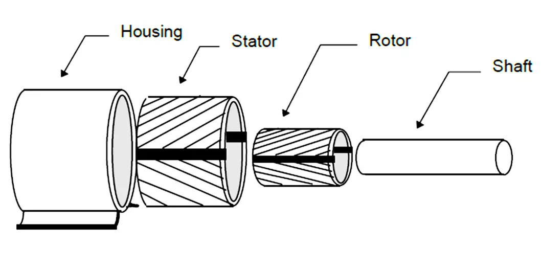
Electric motors are really quite simple. There are only four basic parts to an electric motor:
The electric motor operates by converting electrical energy into mechanical energy.
Let’s represent the motor’s stator as an iron block “S” and the rotor as an iron block “R”. Both of these iron blocks are wrapped with wire coils.
When an electrical current is passed through the wire coils, an electromagnetic field is created and the iron blocks become magnetized.
All magnets have a North and the South Pole. The North Pole is always trying to get next to the South Pole and vice versa.
Two North or two South poles will push away or repel each other. In other words, opposite poles attract, and like poles repel. It’s this magnetic pull and push principle that makes an electric motor operate.
Suppose that “S” is fastened such that it cannot move. On the other hand, “R” is allowed to move freely. When electricity is passed through the coils and the blocks are magnetized, the opposite poles try to pull together.
Block “R” will move towards block “S.” If the blocks get together the movement will stop. What if block “S” were mounted in such a way that block “R” couldn’t contact it? Block “R” would move until its positive pole was as close as it could get to block “S” and then the motion would stop.
Let’s add more “S” blocks (S1, S2, S3, and S4). If S1 were demagnetized just as “R” reached it, and S2 is magnetized, “R” would continue moving toward “S2.” If this same process of demagnetizing and magnetizing S1, then S2, then S3, and finally S4, were continued then block “R” would be moving all the time until it reached S4.
In an electric motor, the “S” magnets are formed in a circle and the “R” magnet is placed inside this circle and is attached to a shaft. The stator and rotor are magnetized as current flows through the coil windings.
The rotor moves so that the opposite poles of the windings can try to move closer to the stator magnets. Just as the magnets are close the magnetic field moves on in the stator, and the rotor chases after it.
Since the rotor and shaft are fastened together, the shaft moves. The rotation of the shaft is the mechanical energy created by the conversion of the electrical energy by the motor.
To summarize, the rotor “chases after” the changing magnetic field of the stator which causes the rotor and shaft to rotate. The magnetic fields of the stator and rotor are changed according to the frequency of the AC voltage applied to the motor.
Changing the frequency of the voltage applied will alter the speed at which the stator’s magnetic fields change. This will, in turn, change the speed of the rotor.
Changing the current will alter the strength of the magnetic fields of the rotor and stator. The stronger the magnetic fields the greater the turning force applied by the rotor to the shaft. This twisting or turning force is called torque.
In this way, we understand the basic fundamentals of an AC motor.
Electrical Drives control the motion of electric motors. Motion control is required in industrial and…
PLC ladder logic design to control 3 motors with toggle switch and explain the program…
VFD simulator download: Master the online tool from the Yaskawa V1000 & programming software for…
The conveyor sorting machine is widely used in the packing industries using the PLC program…
Learn the example of flip-flop PLC program for lamps application using the ladder logic to…
In this article, you will learn the STAR DELTA programming using PLC controller to start…


View Comments
Dear sir /Madam
I am interested to this opportunity l,m interested learn more about instrumentation and so forth.
Thank you
Very beautiful explanation for understanding about torque by motor. Continue your good work.