Hot Wire Anemometer works When an electrically heated wire is placed in a flowing gas stream, heat is transferred from the wire to the gas and hence the temperature of the wire reduces, and due to this, the resistance of the wire also changes. This change in resistance of the wire becomes a measure of flow rate.
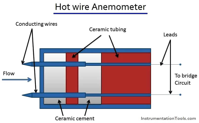
The main parts of the arrangement are as follows:
There are two methods of measuring flow rate using an anemometer bridge combination namely:
The bridge arrangement along with the anemometer has been shown in diagram. The anemometer is kept in the flowing gas stream to measure flow rate.
A constant current is passed through the sensing wire. That is, the voltage across the bridge circuit is kept constant, that is, not varied.
Due to the gas flow, heat transfer takes place from the sensing wire to the flowing gas and hence the temperature of the sensing wire reduces causing a change in the resistance of the sensing wire. (this change in resistance becomes a measure of flow rate).
Due to this, the galvanometer which was initially at zero position deflects and this deflection of the galvanometer becomes a measure of flow rate of the gas when calibrated.
The bridge arrangement along with the anemometer has been shown in diagram. The anemometer is kept in the flowing gas stream to measure flow rate.
A current is initially passed through the wire.
Due to the gas flow, heat transfer takes place from the sensing wire to the flowing gas and this tends to change the temperature and hence the resistance of the wire.
The principle in this method is to maintain the temperature and resistance of the sensing wire at a constant level. Therefore, the current through the sensing wire is increased to bring the sensing wire to have its initial resistance and temperature.
The electrical current required in bringing back the resistance and hence the temperature of the wire to its initial condition becomes a measure of flow rate of the gas when calibrated.
If you liked this article, then please subscribe to our YouTube Channel for Instrumentation, Electrical, PLC, and SCADA video tutorials.
You can also follow us on Facebook and Twitter to receive daily updates.
Read Next:
This article explains how to blink lights in ladder logic with a detailed explanation video…
In this article, a simple example will teach you the conversion from Boolean algebra to…
In this article, you will learn the PLC cooking timer example for kitchen automation using…
Learn an example PLC program to control a pump based on level sensors using ladder…
In the PLC timer application for security camera recording, when motion is detected then camera…
In this example, we will learn batch mixing with PLC ladder logic program using timer…


