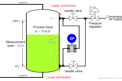
Differential pressure transmitters are very common in the process industries. Besides being used to measure pressure (both differential and gauge), they may also be used to infer fluid level, fluid flow, and fluid density.
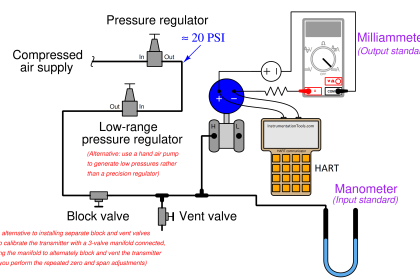
A standard manifold called a three-valve manifold is often used to connect a differential pressure transmitter to the process. These manifolds consist of two block valves (to isolate the “high” and “low” transmitter ports from the process) and one “equalizing” valve (to connect both ports together to ensure zero differential pressure).
Three-valve manifolds are usually found as single units: a billet of metal with valves and ports machined into it, ready to bolt directly to a transmitter. However, you can build your own three-valve manifold using three individual valves, two tee fittings, and whatever other fittings are necessary to connect to the transmitter.
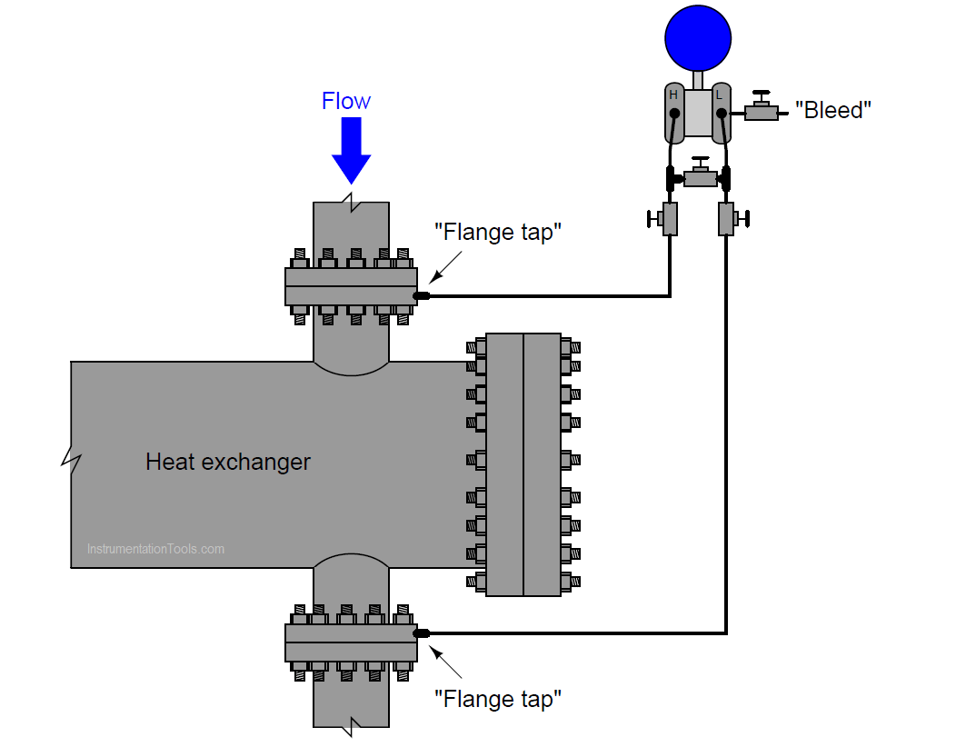
Suppose we encounter a differential pressure transmitter used to measure the pressure drop across a heat exchanger. The typical pressure on the upstream side of this heat exchanger is 1000 PSI, while the typical pressure on the downstream side of this exchanger is 970 PSI. The transmitter connects to this heat exchanger via a three-valve manifold.
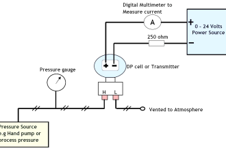
A single “bleed” valve installed on the transmitter’s low-pressure side is used to vent pressure to the atmosphere prior to removal of the transmitter from the manifold:
Differential Pressure Transmitter
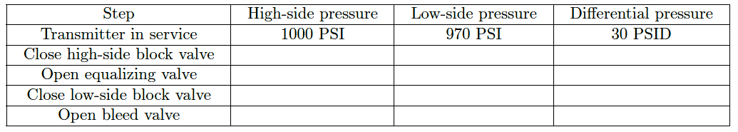
The common procedure for operating a 3-valve manifold to take a transmitter out of service is to first close the high-side block valve, then open the equalizing valve, then close the low-side block valve.
Once these manifold valves have been thus arranged to isolate the transmitter from the process and equalize differential pressure inside the transmitter, the bleed valve may be carefully opened to release stored pressure to the atmosphere.
Determine how much fluid pressure will be on each side of the transmitter through every step of this procedure:
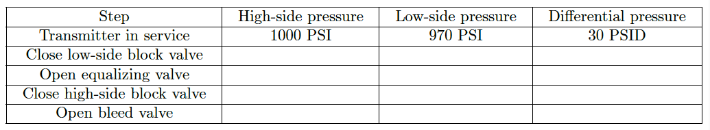
Now, suppose someone else (at a later date) was to remove this transmitter from service using the three-valve manifold, but following a different order of steps: closing the low-side block valve first, then equalizing, then blocking the high side.
Determine how much fluid pressure will be on each side of the transmitter through every step of this (alternative) procedure:
Based on the pressures seen by the transmitter in both procedures, would you recommend one procedure over the other? If so, why?
Share your answers with us through the below comments section.
Read Next:
- DP Transmitter across Baghouse
- Pressure Sensor using Strain Gauge
- Faults in Simple Lamp Circuit
- Micromanometer Pressure Indication
- What is Instrument Air Manifold?
Credits: Tony R. Kuphaldt


this is very powerful and exacellent