This article is about the temperature alarms PLC program for a Gas turbine. Here we will use Siemens TIA PORTAL for programming the logic.
There are many applications in the industry where we need to measure the temperature accurately. If the process temperature goes out of the required range then there must be an alarm generated in the system.
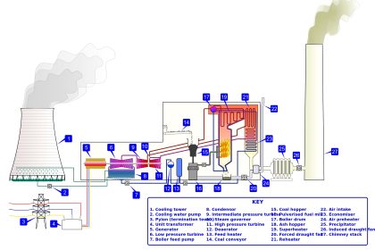
Gas Turbine Temperature Alarms
In a Gas turbine, there are various elements need to be monitored like speed, temperature, lube oil pressure, etc.
Here in this article, let’s consider that in the gas turbine we have to measure the temperature in one of the sections.
Here we will take three temperature sensors where RTD PT 100 is used for its constant high accuracy for a smaller range of the temperature measurement. If anyone of the sensors goes out of the range as per the defined temperature setpoint, there should be an alarm generated, which is to notify personnel that things are not working properly.
Also, we want an average of three sensors to maintain a predefined temperature difference. Let’s say, in our case we need to maintain an average temperature of 100°C. We also need one more alarm to indicate, when the average temperature goes out of the range.
If the Temperature difference between Temperature sensor_1 and the average temperature goes above 100°C then the alarm should be generated. Same applicable for sensor_2 and sensor_3.
Whenever there is an active alarm in the system, then I want an additional GENERAL ALARM to be activated.
Here I will use 3 Analog INPUT’s for three RTD temperature sensors and four outputs, out of them one for average temperature indication and three for individual RTD’s.
Inputs:
- TEMPERATURE SENSOR_1 (MD0)
- TEMPERATURE SENSOR_2 (MD4)
- TEMPERATURE SENSOR_3 (MD8)
Outputs:
- ALARM_1 (Q0.0)
- ALARM_2 (Q0.1)
- ALARM_3 (Q0.2)
- ALARM_4 (Q0.3)
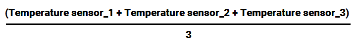
Now first, we need to calculate the average of the temperature readings. For that, we have to add the values of the three temperature sensors and divide it by 3.
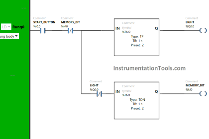
PLC Logic using Siemens TIA Portal

Gas Turbine Temperature Control using Siemens Tia Portal
Program Description
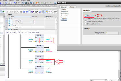
Network 1:
Here, I have added the three temperature sensors readings using ADD instruction and divide it by three as per the above-shown equation to get an average temperature.
Network 2:
Here, we want to generate an alarm, when the difference between Temperature sensor_1 and the average temperature goes above 100 °C. To compare it, we have used greater than instruction.
To generate that difference, I have used subtraction instruction.
Here, absolute instruction is used to reverse the sign (+ or -). If the temperature difference goes negative, we want it to positive using absolute instruction. So, it only alarms when the temperature goes above 100 °C.
Absolute instruction only uses real data type. That’s why we have used data type “real” in all the instructions.
Network 3 & 4:
Here, as explained in the above network Alarm_2 and Alarm_3 generated if the temperature goes above 100°C.
Network 5:
As the temperature difference goes above 100°C from any one of the sensors then the main alarm will also generate.
Author: Suhel Patel
If you liked this article, then please subscribe to our YouTube Channel for PLC and SCADA video tutorials.
You can also follow us on Facebook and Twitter to receive daily updates.
Read Next:
- Troubleshoot PLC Program
- Lube Oil Pump Logic
- PLC Maths Instructions
- What is PID Controller?
- PID Controller Loop Tuning


GOOD, THANK YOU VERY MUCH