Gage and Absolute Pressure Transmitters :

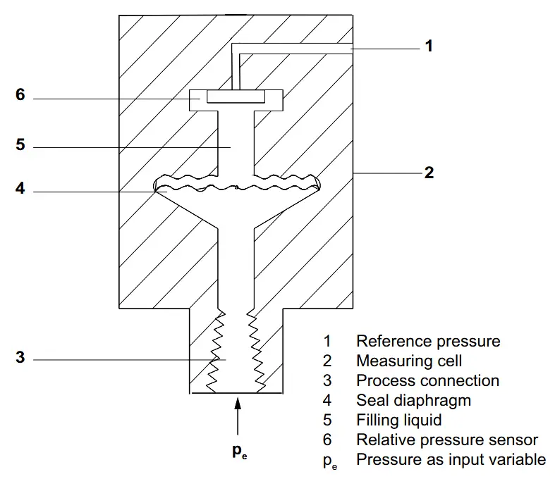
The input pressure (pe) is transferred to the gage pressure sensor (6) via the seal diaphragm (4) and the filling liquid (5), displacing its measuring diaphragm.
The displacement changes the resistance value of the four piezo resistors in the measuring diaphragm in a bridge circuit.
The change in the resistance causes a bridge output voltage proportional to the input pressure.
The transmitters with spans ≤ 63 bar measure the input pressure against atmosphere, those with spans ≥ 160 bar against vacuum.
The input pressure (pe) is transferred to the absolute pressure sensor (5) via the seal diaphragm (3) and the filling liquid (4), displacing its measuring diaphragm.
The displacement changes the resistance value of the four piezo resistors in the measuring diaphragm in a bridge circuit.
The change in the resistance causes a bridge output voltage proportional to the input pressure.
The input pressure is converted into an electrical signal by the sensor (1). This signal is amplified by the measuring amplifier (2) and digitalized in an analog to digital converter (3). The digital signal is analyzed in a microcontroller (4) and corrected with regard to linearity and thermal characteristics.
In a digital to analog converter (5) it is then converted into the output current of 4 to 20 mA. A diode circuit provides reverse voltage protection. You can make an uninterrupted current measurement with a low ohm ammeter at the connection (10).
The data specific to the measuring cell, the electronic data and parameter settings are stored in two non-volatile memories (6). The first memory is linked with the measuring cell, the second with the electronics.
The buttons (8) can be used to call up individual functions, socalled modes. If you have a device with a digital display (9), you can use this to track mode settings and other messages. The basic mode settings can be changed with a computer via the HART modem (7).
Reference : Siemens Manual, Image Credits : Siemens
Learn the example of flip-flop PLC program for lamps application using the ladder logic to…
In this article, you will learn the STAR DELTA programming using PLC controller to start…
Lube oil consoles of rotary equipment packages in industrial process plants are usually equipped with…
Rotating equipment packages such as pumps, compressors, turbines need the lube oil consoles for their…
This article explains how to blink lights in ladder logic with a detailed explanation video…
In this article, a simple example will teach you the conversion from Boolean algebra to…
View Comments
Very useful information.
But sir how to identify that it is Rosemont gauge pressure or absolute pressure transmitter in 2051c series.