Differences between PCB and PCBA
SMT is referred to as “bare circuit board” (PCB) and “circuit board plug-in assembly” (PCBA). One is a finished board, and the other is an unfinished board.
PCB (Printed Circuit Board), consisting of epoxy glass resin material, is separated into 4, 6, and 8 layers depending on the number of signal layers. Four and six layers are the most prevalent counts.
Chip components, including chips, are mounted to the bare board. A finished circuit board, or PCBA, can only be created after the circuit board manufacturing process is complete. PCBA is short for printed circuit board assembly.
One of the most popular and likely easiest to comprehend components on PCBs are various resistors including linear and non-linear resistors. Their purpose is to block the flow of electricity by converting electrical energy into heat.
Overview of Printed Circuit Board (PCB)
Due to their superior mechanical and electrical properties, PCBs are the best option for these applications. Today, rigid PCBs make up around 90% of all PCB production, making them the most prevalent type of PCB globally.
Because some PCBs are flexible, the circuitry can be bent and stretched into place. Flexible circuits are also used in applications where they can sustain millions of bend cycles without breaking. These flexible PCBs account for around 10% of the market.
A tiny subset of these kinds of circuits are referred to as rigid-flex circuits, which have firm parts of the board that are perfect for mounting and connecting components and flexible parts that offer the benefits of flexible circuits that were previously mentioned.
If you are still unable to know what is the PCB, you can have look at our electronic platform, which owns many electronic parts and many excellent blog posts.
Five Types of PCB Assembly
- Rigid-flex printed circuit board assembly
- Mixed assembly
- Through-hole assembly
- BGA assembly
- SMT assembly
Rigid-flex Printed Circuit Board Assembly
What is Rigid-Flex PCBA?
Rigid-flex boards are printed circuit boards that combine rigid and flexible board technologies.
The majority of rigid-flex boards are constructed from numerous layers of flexible circuit substrates that are externally or internally linked to one or more rigid boards, depending on the design of the application.
The flexible substrates are designed to be in a constant state of flexibility and are often moulded into the flexed curve during manufacturing or installation.
The advantages of Rigid-Flex PCBA
- Simple modular interfaces to the system environment are provided by integrated ZIF contacts.
- Simpler test conditions are used. a thorough test is conducted before installation is possible.
- Rigid-Flex boards greatly lower the cost of logistics and assembly.
- The degree of freedom for appropriate housing solutions can be increased by making mechanical designs more complex.
Mixed assembly
What is the Mixed Assembly?
Despite the fact that surface mount technology has supplanted other mounting methods in PCB production, some components still cannot be assembled using SMT technology.
Then, both SMT and THT assembly must be performed on the same board. A mixture of assembly methods without the use of solder paste during production is referred to as a mixed assembly.
Although some specialized components that are not available through the SMT process must be assembled using mixed PCB, the majority of the components are welded in surface mount configuration on the board.
The Advantages of Mixed Assembly
- Small-quantity PCB board components include all varieties of BGAs, QFNs, CSPs, 0201, 01005, POP, and Pressfit Components.
- SMT and through-hole polarized capacitors are examples of part polarity capacitors.
- The capacity to remove and replace BGAs and MBGAs, as well as having knowledge of ceramic and plastic BGAs, are all examples of rework capabilities.
Through-hole Assembly
What is a Through-hole Assembly?
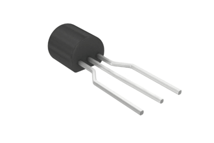
The through-hole assembly method, in which the components are placed using leads, is used to build electronic circuits. It explains the installation process in which the components are attached to the board using either wave soldering or manual soldering after the leads are put into the pre-drilled holes.
Over time, single-sided, double-sided, and ultimately multi-layer boards were used in PCB design. It is difficult to modify through-hole assembly to meet the requirements of modern electronics.
SMT technology has essentially replaced through-hole assembly in the manufacture of PCBs today. However, some applications still need through-hole installation, such as those involving electrolytic capacitors, connectors, and large transformers.
The Advantages and Disadvantages of Through-hole Assembly
High reliability
Through-hole assemblies generate more environmental stress because leads must be put into the holes to bind the components to the board, as compared to SMT components, which are simply soldered on the PCB’s surface.
Through-hole assembly, which offers a stronger physical connection as a result, is chosen by the aerospace industry and the military because both organizations have high dependability requirements.
Higher durability
Because of their high-stress tolerance and good heat resistance, through-hole components are frequently used in industrial machinery and equipment.
Due to their strength and brightness, through-hole LEDs are employed in the LED lights on huge billboards.
BGA Assembly
What is BGA?
Ball grid arrays (BGA), often known as chip carriers, are surface-mount devices used to package integrated circuits. BGA packaging is used to permanently install devices like microprocessors.
A dual in-line or flat package cannot hold as many connector pins as a BGA can. The full bottom surface of the device can be utilized rather than just the edge.
The traces connecting the package’s leads to the wires or balls that connect the die to the package are often shorter in a perimeter-only type than in another, which enhances performance at high speeds.
The Advantages of the BGA Assembly
Higher-density circuits
Through-hole circuits got more densely populated, making it practically impossible to solder them precisely without crossover or short circuits.
Heat conduction
BGA circuits minimize overheating issues by facilitating significantly easier heat transfer from the integrated circuit externally.
SMT Assembly
What is the SMT Assembly?
Its full name is surface mount technology or SMT. SMT is a method of joining components or parts to circuit boards.
SMT’s higher outcomes and increased efficiency have forced other PCB assembly techniques to be replaced. The majority of the time in the past, PCB manufacturers added components using through-hole assembly.
However, SMT has replaced the prior assembling method with welding technology.
Additionally, PCBs created utilizing the SMT assembly process are used in all electronic industries, including those in computers, phones, smartphones, household appliances, etc.
The fundamental steps of SMT assembly include mounting components, reflow soldering, printing solder paste, and performing AOI or AXI.
The Advantages of SMT Assembly
Cost-saving
Automated machinery is frequently utilized during SMT assembly. Automatic machines help to reduce manual steps during SMT operations, which significantly improves production productivity and, over time, lowers labor costs, despite the fact that the machines’ input costs are high.
The through-hole assembly also saves money since it uses fewer materials.