Inst ToolsInst ToolsInst Tools
  • Courses
  • Automation
    • PLC
    • Control System
    • Safety System
    • Communication
    • Fire & Gas System
  • Instrumentation
    • Design
    • Pressure
    • Temperature
    • Flow
    • Level
    • Vibration
    • Analyzer
    • Control Valve
    • Switch
    • Calibration
    • Erection & Commissioning
  • Interview
    • Instrumentation
    • Electrical
    • Electronics
    • Practical
  • Q&A
    • Instrumentation
    • Control System
    • Electrical
    • Electronics
    • Analog Electronics
    • Digital Electronics
    • Power Electronics
    • Microprocessor
  • Request
Search
  • Books
  • Software
  • Projects
  • Process
  • Tools
  • Basics
  • Formula
  • Power Plant
  • Root Cause Analysis
  • Electrical Basics
  • Animation
  • Standards
  • 4-20 mA Course
  • Siemens PLC Course
Reading: FIFO Instruction in Allen Bradley PLC Programming
Share
Font ResizerAa
Inst ToolsInst Tools
Font ResizerAa
  • Courses
  • Design
  • PLC
  • Interview
  • Control System
Search
  • Courses
  • Automation
    • PLC
    • Control System
    • Safety System
    • Communication
    • Fire & Gas System
  • Instrumentation
    • Design
    • Pressure
    • Temperature
    • Flow
    • Level
    • Vibration
    • Analyzer
    • Control Valve
    • Switch
    • Calibration
    • Erection & Commissioning
  • Interview
    • Instrumentation
    • Electrical
    • Electronics
    • Practical
  • Q&A
    • Instrumentation
    • Control System
    • Electrical
    • Electronics
    • Analog Electronics
    • Digital Electronics
    • Power Electronics
    • Microprocessor
  • Request
Follow US
All rights reserved. Reproduction in whole or in part without written permission is prohibited.
Inst Tools > Blog > PLC Tutorials > FIFO Instruction in Allen Bradley PLC Programming

FIFO Instruction in Allen Bradley PLC Programming

Last updated: March 4, 2021 12:09 pm
Editorial Staff
PLC Tutorials
No Comments
Share
6 Min Read
SHARE

What Is FIFO in Rockwell PLC Programming? 

FIFO is a special programming instruction that can be used in the applications that require to store the sequence of data in order and unload it.

FIFO Instruction

Now we are gonna see how are loading and unloading done in FIFO.

FFL and FFU instructions

Yes! FIFO should be used in a pair. There should be an instruction to load and there should be an instruction to unload.

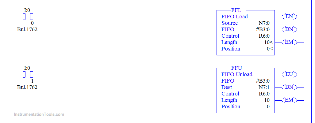
The following are the block parameters in FIFO load instruction,

Source:

Here is where one should give an address where the values to be loaded are present.

FIFO:

Here is where one should specify the address where the values have to be loaded. This address seems weird right with an ‘#’ in the front. When we use an ‘#’ symbol in the front it is called an array of addresses.

Obviously there will be a sequence of values present to be loaded arrays are capable of storing many values right? So why we gave ‘#’ in the front should make sense now.

Control:

Here is where one should specify the control address. In Rockwell PLC programming environment there is a separate address for the control with R6:0 as starting one. So when the FIFO load is done loading the values the R6:0 address gives us a true bit.

Length:

Here is where we have to specify the length of the array so that the array of address prepares them for loading the values.

Position:

Here is where we have to give the index number of an array from where the loading has to start. I’ll leave it to 0 so the loading starts from the 0th index.

The following are the block parameters in FIFO unload instruction,

  • FIFO – Here is where one has to give the address where the values to be unloaded are present. So obviously both the load and unload has the same address in here.
  • Dest – Here is where one has to give the address where the values have to be unloaded.
  • Control, Length, and Position carry the same explanation from the FIFO load.

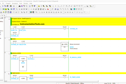
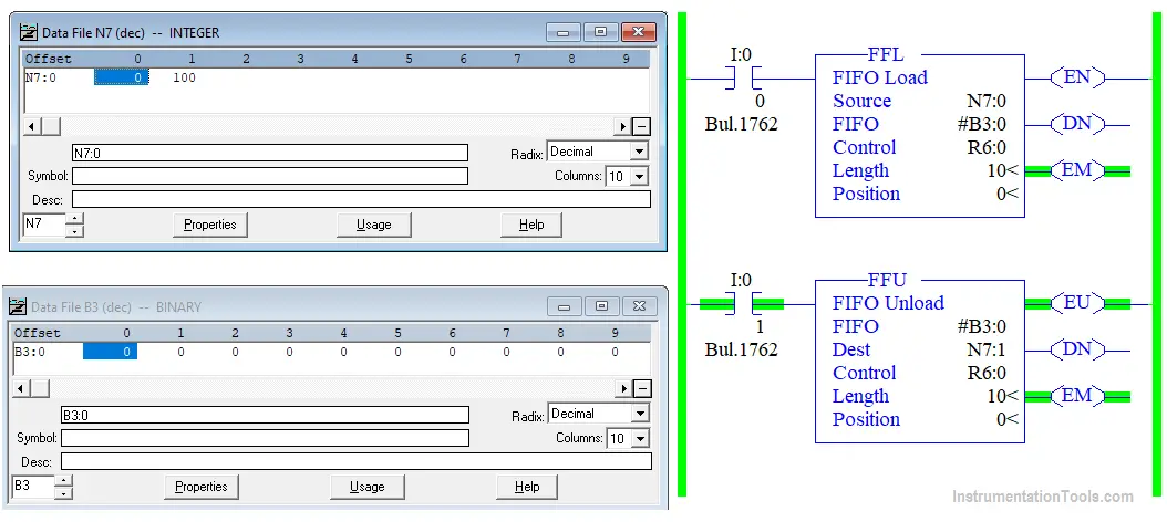
Now we’re going to the run time to see how the loading and unloading happens,

Load and Unload Instructions for Allen Bradley PLC

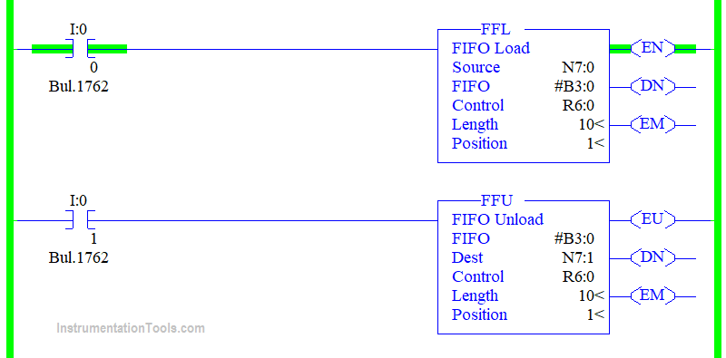
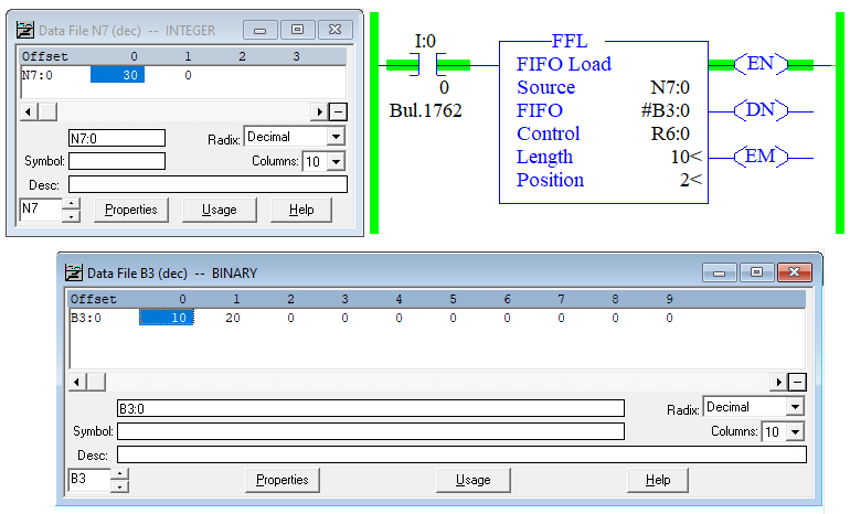
Now we are on the run time and when the input to FFL is made to turn on the value on N7:0 gets loaded to the array address #B3:0. B3:0 is a binary address to view the value as decimal change the radix to decimal.

Refer to the below figure for the first loaded value.

RS Logix 500 FIFO Function Data File

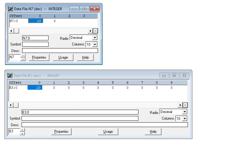
You can also see the number of lengths we specified is 10 and the Binary data file shows us from 0 to 9.

Here is the next loaded value.

RSLogix 5000 FIFO Load and Unload
RSLogix 5000 FIFO Data File

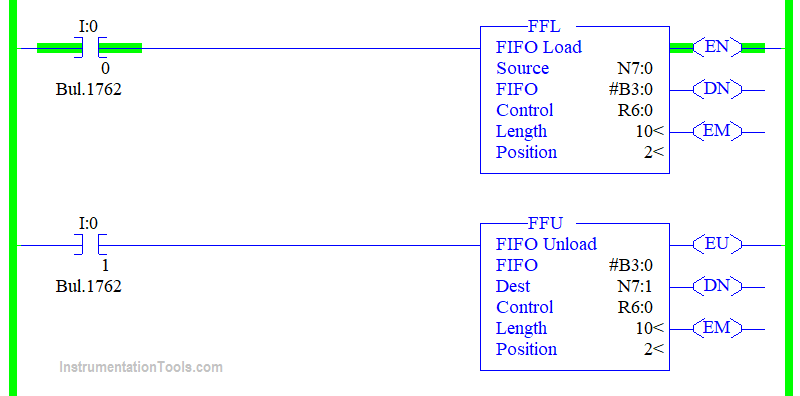
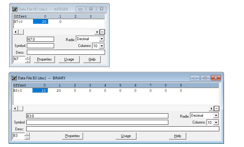
You can see that the position is increasing in the FFL and FFU as the value is getting loaded. So the value is getting loaded from left to right the starting position is 0 and the ending is 9.

Also, notice that the value gets loaded for each false to the true transition of the rung. Refer to the below figure.

RSlogix 500 fifo example

You can see that I have changed the source address value to 30 but it is not getting loaded since the rung is staying true once the rung becomes false and true again then the value gets loaded.

Tutorial on FIFO instruction of Allen Bradley PLC

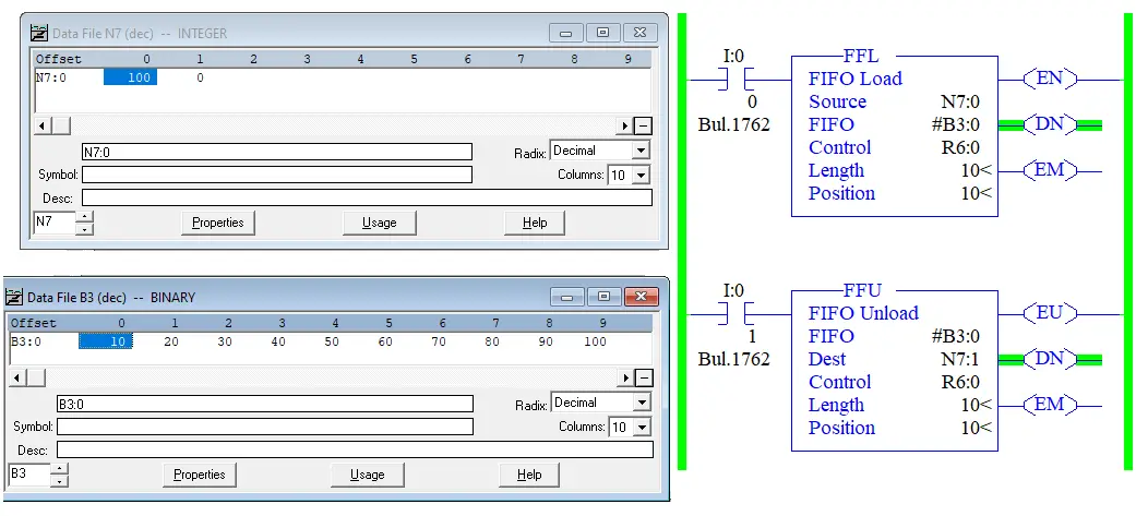
So we have completed loading the values now the Position is at 10 and the done bit does to the true state.

Now we are going to look at the unloading of the data,

PLC FIFO Instruction

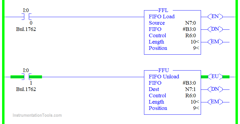
Now I made the FFU rung true you can notice that the done bit goes OFF again.

AB PLC First in First out

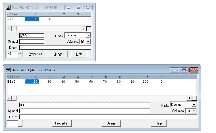
Also, notice that the value which got loaded first comes out first. So the expansion of FIFO is called First in First Out. The one which came first unloads first.

Likewise, whenever the rung makes false to true transition each value unloads in a manner that which came first goes out. So the last value which comes out should be 100.

PLC Training Data Tables FIFO and LIFO

You can also notice from the figure that the empty bit goes up when the values on the FIFO address become empty.

An example of a real-time application where FIFO is used might be tracking parts through an assembly line where parts are represented by values that have a part number and assembly code.

Author: Abishek D

If you liked this article, then please subscribe to our YouTube Channel for PLC and SCADA video tutorials.

You can also follow us on Facebook and Twitter to receive daily updates.

Read Next:

  • PLC Midline Instruction
  • Namur Digital Input Card
  • Allen Bradley Powerflex VFD
  • PLC Batch Process Program
  • Heuristic PID Tuning
Don't Miss Our Updates
Be the first to get exclusive content straight to your email.
We promise not to spam you. You can unsubscribe at any time.
Invalid email address
You've successfully subscribed !

Continue Reading

How to Read an Electrical Wiring Diagram?
Sequential Operation of Output Bits using Two Push buttons
Parts of PLC
PLC Programming Best Practices and Tips
STL Programming – SET, RESET, ASSIGN
Scaling with Parameters (SCP) Instruction in PLC
Share This Article
Facebook Whatsapp Whatsapp LinkedIn Copy Link
Share
Leave a Comment

Leave a Reply Cancel reply

Your email address will not be published. Required fields are marked *

Stay Connected

128.3kFollowersLike
69.1kFollowersFollow
210kSubscribersSubscribe
38kFollowersFollow

Categories

Explore More

Control Loops Objective Questions and Answers
Run 4 Motors Sequentially from Same Push button PLC Program
Motor Trip Logic using PLC Programming
OFF Delay Timer using PLC
Types of Digital Outputs in PLC
How to Design a Motor Faceplate in Graphics? – SCADA Tutorials
Parking Garage Indicator: PLC Automation System
Communicating Between Siemens PLC and Other PLC Brands

Keep Learning

Ferrule Example

Ferrules and Cross Ferruling

PLC Data comparison instructions

PLC Data Comparison Instructions

Free WinCC SCADA Training Course

Free SCADA Training Course

PLC Tag Naming Conventions

PLC Tag Naming Conventions

Types of PLC

#14 PLC Best Practices – Restrict Third-party Data Interfaces

Simulating Level Sensor and the Pump Logic in PLC

PLC Basics – Manual Control, Closed Loop, ON-OFF with Hysteresis

MODBUS ASCII Communication Protocol Explained

MODBUS ASCII Communication Protocol Explained

Scan cycle of a Siemens PLC

OB1 – Main Cyclic Organization Block in TIA Portal

Learn More

Flow Measurement Questions

MCQ on Flow Measurement

Electromagnetic Flow Meters Working Principle

Power Electronics Objective Questions

Dual Converters Objective Questions

Switch or Transmitter

Switch or Transmitter

Instrumentation and Control Project Packages

Instrumentation and Control Project Packages – Detail Engineering

Asynchronous Motor Animation

Asynchronous Motor Animation

Vibration Probe Field Setting Procedure

Vibration Probe Field Setting Procedure

Parallel RLC Circuit

Resonance, Resonant Frequency, Series and Parallel Resonance

Menu

  • About
  • Privacy Policy
  • Copyright

Quick Links

  • Learn PLC
  • Helping Hand
  • Part Time Job

YouTube Subscribe

Follow US
All rights reserved. Reproduction in whole or in part without written permission is prohibited.
Welcome Back!

Sign in to your account

Username or Email Address
Password

Lost your password?