Let us consider a liquid level control system on an open tank, where three different fluid ingredients (shown in the following P&ID simply as A, B, and C) are mixed to produce a final product. A level transmitter (LT) measures liquid level, while a level controller (LC) compares this level to a setpoint value, and outputs a signal calling for a certain amount of discharge flow. A cascaded (slave) flow controller (FC) senses outgoing flow via a flow transmitter (FT) and works to maintain whatever rate of flow is “asked” for by the level controller:
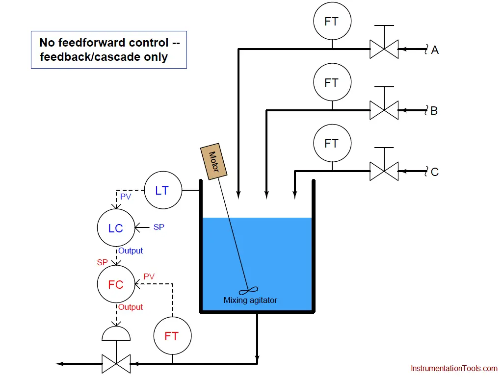
The level control system acts to keep liquid level constant in the vessel, ensuring adequate mixing of the three ingredients. Being a feedback level control system, it adjusts the discharge flow rate in response to measured changes in liquid level. Like all feedback control systems, this one is reactive in nature: it can only take corrective action after a deviation between process variable (level) and setpoint is detected. As a result, temporary deviations from setpoint are guaranteed to occur with this control system every time the combined flow rate of the three ingredients increases or decreases.
Let us now change the control system strategy from feedback to feedforward. It is clear what the loads are in this process: the three ingredient flows entering the vessel. If we measure and sum these three flow rates, then use the total incoming flow signal as a setpoint for the discharge flow controller, the outlet flow should (ideally) match the inlet flow, resulting in a constant liquid level. Being a purely feedforward control system, there is no level transmitter (LT) any more, just flow transmitters measuring the three loads:
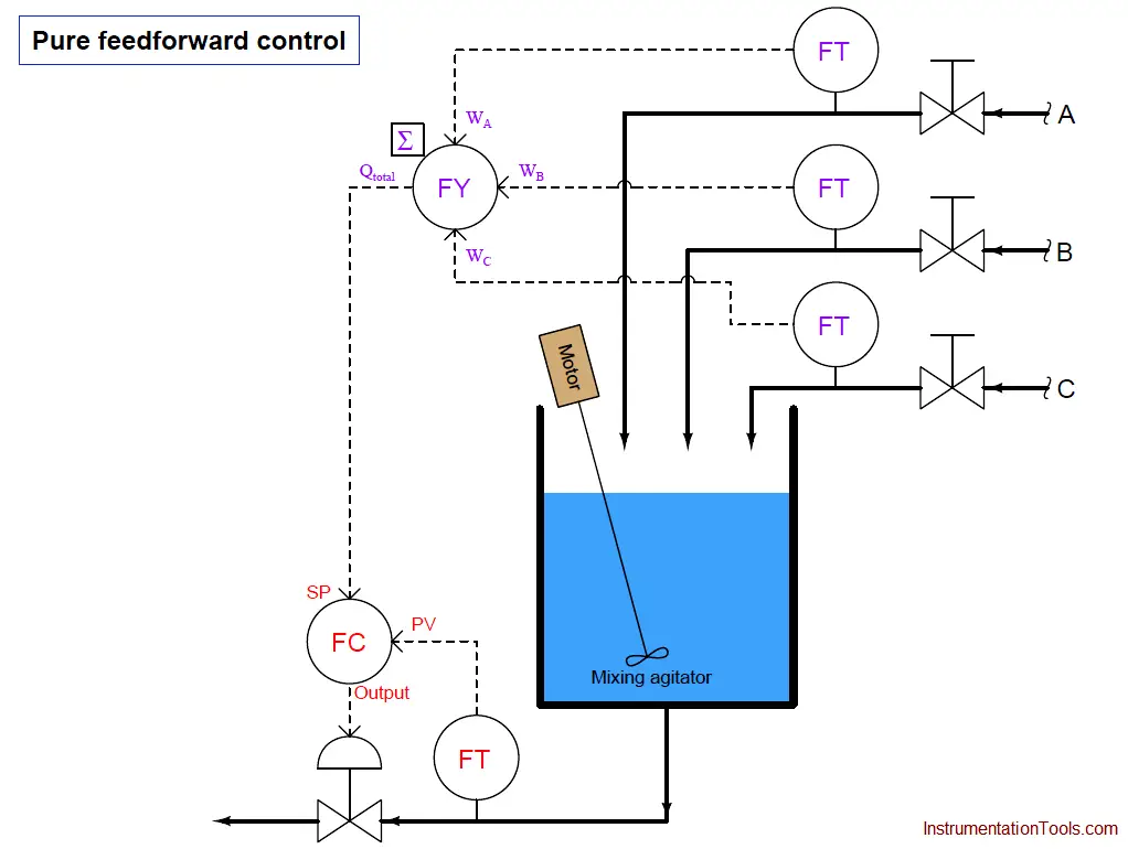
If all flow transmitter calibrations are perfect, the summing of flow rates flawless, and the flow controller’s tuning robust, this level control system should control liquid level in the vessel by proactive effort (“thinking ahead”) rather than reactive effort (“after the fact”). Any change in the flow rate of ingredients A, B, and/or C is quickly matched by an equal adjustment to the discharge flow rate. So long as total volumetric flow out of the vessel is held equal to total volumetric flow into the vessel, the liquid level inside the vessel cannot change.
If this feedforward strategy reminds you of ratio control, you are thinking correctly: the ingredient flow sum signal is the wild variable, and the discharge flow signal is the captive variable. The flow controller simply maintains the discharge flow rate at a 1:1 ratio with the (total) ingredient flow rate. In fact, pure feedforward control is a variation of 1:1 ratio control, except that the real process variable (tank level) is neither the wild (total incoming flow) nor the captive variable (discharge flow) in the process.
Also Read : Feedback Control Principle
An interesting property of feedforward and ratio control systems alike is that they cannot generate oscillations as is the case with an over-tuned (excessive gain) feedback system. Since a feedforward system does not monitor the effects of its actions, it cannot react to something it did to the process, which is the root cause of feedback oscillation. While it is entirely possible for a feedforward control system to be configured with too much gain, the effect of this will be overcompensation for a load change rather than oscillation. In the case of the mixing tank feedforward level control process, improper instrument scaling and/or offsets will merely cause the discharge and inlet flows to mismatch, resulting in a liquid level that either continues to increase or decrease over time (“integrate”). However, no amount of mis-adjustment can cause this feedforward system to produce oscillations in the liquid level.
In reality, this pure feedforward control system is impractical even if all instrument calibrations and control calculations are perfect. There are still loads unaccounted for: evaporation of liquid from the vessel, for example, or the occasional pipe fitting leak. Furthermore, since the control system has no “knowledge” of the actual liquid level, it cannot make adjustments to that level. If an operator, for instance, desired to decrease the liquid level in order to reduce the residence time (also known as “retention time”) , he or she would have to manually drain liquid out of the vessel, or temporarily place the discharge flow controller in “manual” mode and increase the flow there (then place back into “cascade” mode where it follows the remote setpoint signal again). The advantage of proactive control and minimum deviation from setpoint over time comes at a fairly high price of impracticality and inconvenience.
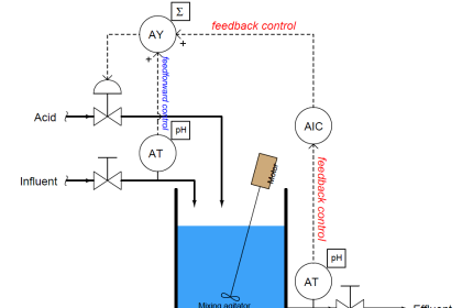
For these reasons, feedforward control is most often found in conjunction with feedback control. To show how this would work in the liquid level control system, we will incorporate a level transmitter and level controller back into the system, the output of that level controller being summed with the feedforward flow signal (by the LY summing relay) before going to the cascaded setpoint input of the discharge flow controller:
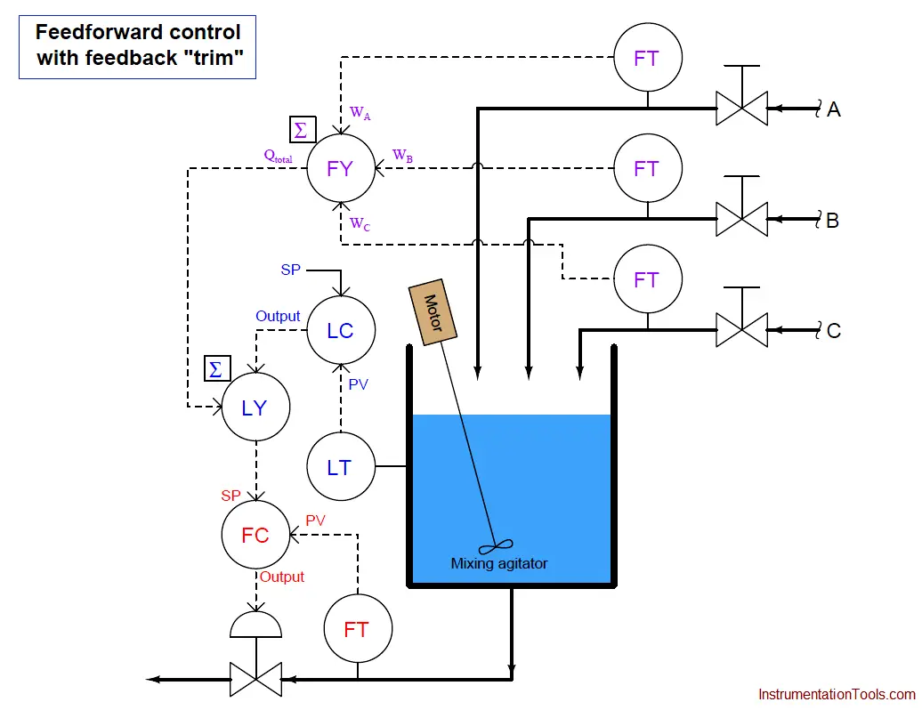
This hybrid control strategy is sometimes called feedforward with trim. In this context, “trim” refers to the level controller’s (LC) output signal contributing to the discharge flow setpoint, helping to compensate for any unaccounted loads (evaporation, leaks) and provide for level setpoint changes. This “trim” signal should do very little of the control work in this system, the bulk of the liquid level stability coming from the feedforward signals provided by the incoming flow transmitters.
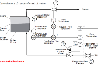
A very similar control strategy commonly used on large steam boilers for the precise control of steam drum water level goes by the name of three-element feedwater control.
Such a control system is called “three-element” because it makes use of three process measurements:
- Feedwater flow rate
- Steam drum water level
- Steam flow rate
Read Boiler three element control principle. CLICK HERE.