Electronic Pressure Transmitters / Sensors Principle
Most electronic pressure sensors incorporate different elements as the primary pressure detector, and it is used to vary a measurable electrical quantity to produce a proportionately variable electronic signal.
Because the energy form is transferred from a mechanical to an electrical nature, these devices are often classified as transducer.
Generally, electrical pressure detectors are more accurate and have much faster response times. This is due in part to the accuracy of their electronic circuitry and in part to the extremely small movement required to the elastic elements in order to obtain the needed electrical change.
The reduced movement very nearly eliminates drift, friction and hysteresis common to bellows, diaphragm and bourdon elements that require relatively large movements..
Capacitance Pressure Sensor
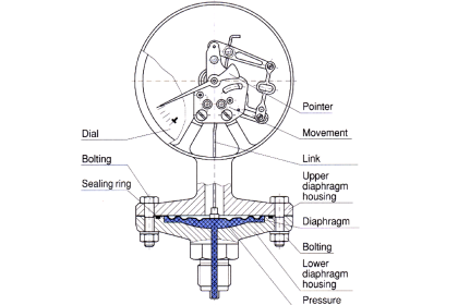
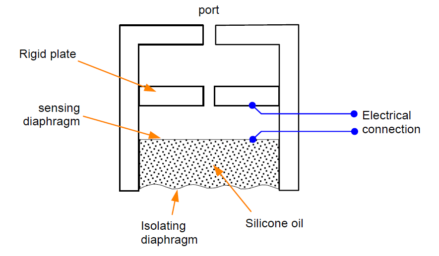
The capacitance pressure sensor operates on the principle that, if the sensing diaphragm between two capacitor plates is deformed by a differential pressure, an imbalance of capacitance will occur between itself and the two plates.
This imbalance is detected in a capacitance bridge circuit and converted to a D.C. output current of 4 to 20 mA.
This is shown in Figure, where the movement of a flexible diaphragm relative to a fixed plate is sensed by the capacitance change. A secondary isolating diaphragm is used to protect the sensing diaphragm.
Another type of capacitor uses concentric hollow metal cylinders. The capacitance of this type just like the fiat-plate type is proportional to the area.
This principle can be applied to differential pressure measurement, as shown in Figure. The pressure acting on the isolating diaphragms set up similar pressures in the silicone oil filling the space between them.
A net force proportional to the difference between the two pressures acts upon the metal sensing diaphragm and deflects it to one side or the other, depending on which input pressure is the greater.
Each plate forms a capacitor with the sensing diaphragm, which is connected electrically to the metallic body transducer.
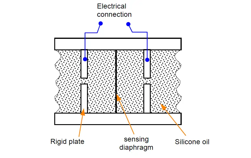
The sensing diaphragm and capacitor thus form a differential variable separation capacitor. When the two input pressure are equal, the diaphragm is positioned centrally and the capacitances are equal.
A difference in the two input pressures causes displacement of the sensing diaphragm and is sensed as a difference between the two capacitances.
Strain Gauge Pressure Sensor
Strain is defined as a deformation or change in the shape of a material as a consequence of applied forces.
A strain gauge is a device which uses the change of electrical resistance of a wire under strain to measure pressure.
The strain gauge changes a mechanical motion into an electrical signal when a wire length is changed by tension or compression, altering the wire diameter and, hence, changing the electrical resistance.
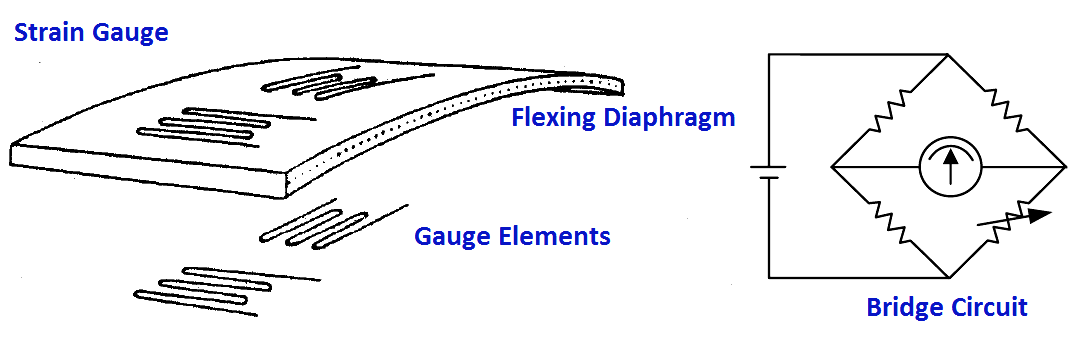
The change in resistance is a measure of the pressure producing the mechanical distortion. This is measured by a Wheatstone bridge circuit, preferably of the null balance type, so that the strain gauge carries no current.
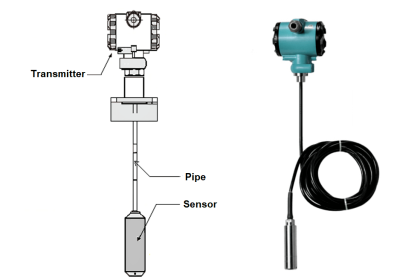
The complete measuring device includes a sensing element ( bourdon tube, bellows or diaphragm ), a strain gauge attached to the element, a stable power source and a read out device.
A strain gauge element and a typical transducer is shown in the figure below
Piezo Electric Pressure Sensor
Piezoelectricity is defined as the production of an electric potential due to pressure on certain crystalline substances such as quartz, Rochelle salt, tourmaline, barium titanate, ammonium dehydrogen phosphate and other ceramic crystals.
This piezoelectric effect is used for measurement of pressure, force or acceleration. The primary interest here is in its use as a pressure sensor.
Quartz is the most commonly used crystal that produces the piezoelectric effect. Synthetic crystals have been developed that produce the same effect and they generally have higher sensitivities than natural crystals.
The nature of the piezoelectric device is the production of electric potential as it is deformed or stressed. In a static condition, its potential drops off, producing an error.
This characteristics limits its used somewhat. As a pressure device, it is most useful were pressure variations occur frequently.
It is particularly suited for measurement of pressure transients in ballistics, in internal combustion engines or in reaction processes where pressures change quickly.
Major advantages of piezoelectric devices are the linear relationship between pressure variation and output voltage and their high frequency response ( as high as 106 Hz for quartz ).
A decide advantage of the piezoelectric device is its sensitivity to temperature variations. Reproducible results are not obtained unless temperatures are kept within close limits.
Credits : N Asyiddin