Inst ToolsInst ToolsInst Tools
  • Courses
  • Automation
    • PLC
    • Control System
    • Safety System
    • Communication
    • Fire & Gas System
  • Instrumentation
    • Design
    • Pressure
    • Temperature
    • Flow
    • Level
    • Vibration
    • Analyzer
    • Control Valve
    • Switch
    • Calibration
    • Erection & Commissioning
  • Interview
    • Instrumentation
    • Electrical
    • Electronics
    • Practical
  • Q&A
    • Instrumentation
    • Control System
    • Electrical
    • Electronics
    • Analog Electronics
    • Digital Electronics
    • Power Electronics
    • Microprocessor
  • Request
Search
  • Books
  • Software
  • Projects
  • Process
  • Tools
  • Basics
  • Formula
  • Power Plant
  • Root Cause Analysis
  • Electrical Basics
  • Animation
  • Standards
  • 4-20 mA Course
  • Siemens PLC Course
Reading: Electron Gun of Cathode Ray Tube
Share
Font ResizerAa
Inst ToolsInst Tools
Font ResizerAa
  • Courses
  • Design
  • PLC
  • Interview
  • Control System
Search
  • Courses
  • Automation
    • PLC
    • Control System
    • Safety System
    • Communication
    • Fire & Gas System
  • Instrumentation
    • Design
    • Pressure
    • Temperature
    • Flow
    • Level
    • Vibration
    • Analyzer
    • Control Valve
    • Switch
    • Calibration
    • Erection & Commissioning
  • Interview
    • Instrumentation
    • Electrical
    • Electronics
    • Practical
  • Q&A
    • Instrumentation
    • Control System
    • Electrical
    • Electronics
    • Analog Electronics
    • Digital Electronics
    • Power Electronics
    • Microprocessor
  • Request
Follow US
All rights reserved. Reproduction in whole or in part without written permission is prohibited.
Inst Tools > Blog > Electronic Devices & Circuits > Electron Gun of Cathode Ray Tube

Electron Gun of Cathode Ray Tube

Last updated: April 1, 2018 8:27 am
Editorial Staff
Electronic Devices & Circuits
No Comments
Share
3 Min Read
SHARE

This post is the continuation of the previous post on cathode ray tube.

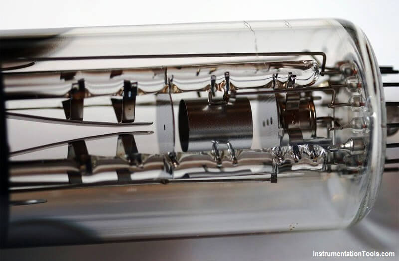
The electron gun section of the cathode ray tube provides a sharply focused electron beam directed towards the fluorescent-coated screen. This section starts from thermally heated cathode, emitting the electrons. The control grid is given negative potential with respect to cathode. This grid controls the number of electrons in the beam, going to the screen.

Electron Gun of CRT

The momentum of the electrons (their number * their speed) determines the intensity, or brightness, of the light emitted from the fluorescent screen due to the electron bombardment. The light emitted is usually of the green color. Because the electrons are negatively charged, a repulsive force is created by applying a negative voltage to the control grid (in CRT, voltages applied to various grids are stated with respect to cathode, which is taken as common point). This negative control voltage can be made variable.

Electron Gun of Cathode Ray Tube

Note: a more negative voltage results in less number of electrons in the beam and hence decreased brightness of the beam spot.

Since the electron beam consists of many electrons, beam tends to diverge. This is because the similar (negative) charges on the electron repel each other. To compensate for such repulsion forces, an adjustable electrostatic field is created between two cylindrical anodes called the focusing anodes.

Note: the variable positive voltage on the second anode is used to adjust the focus or sharpness of the bright beam spot.

The high positive potential is also given to the preaccelerating anodes and accelerating anodes, which results into the required acceleration of the electrons.

Both focusing and accelerating anodes are cylindrical in shape having small openings located in the center of each electrode, co-axial with the tube axis. The preaccelerating and accelerating anodes are connected to a common positive high voltage which varies between 2 kV to 10 kV. The focusing anode is connected to a lower positive voltage of about 400V to 500V.

In the next post I will explain about the deflection system of cathode ray tube.

Don't Miss Our Updates
Be the first to get exclusive content straight to your email.
We promise not to spam you. You can unsubscribe at any time.
Invalid email address
You've successfully subscribed !

Continue Reading

Diode Limiters/Clippers Operation
Transistor Emitter Bias
Characteristics of Photo diode
What is Kirchhoff’s Current Law
Basic Transistor Amplifier Circuit Principle
Half Wave Rectifier Principle
Share This Article
Facebook Whatsapp Whatsapp LinkedIn Copy Link
Share
Leave a Comment

Leave a Reply Cancel reply

Your email address will not be published. Required fields are marked *

Stay Connected

128.3kFollowersLike
69.1kFollowersFollow
210kSubscribersSubscribe
38kFollowersFollow

Categories

Explore More

Series and Parallel Resistors
CRT Fluorescent Screen
Basics of Ohm’s Law
Classification of Bridge Circuits
Positive & Negative Diode Clippers
Ripple Voltage in Rectifiers
Amplifiers Questions & Answers
Full Wave Rectifier

Keep Learning

energy-diagrams-for-insulator-semiconductor-and-conductor

Band Gap for Semiconductor Materials

Combining Independent Current Sources in Parallel

Combining Independent Current Sources in Parallel

Comparison of Half wave Rectifiers and Full wave Rectifiers

Comparison of Half wave Rectifiers and Full wave Rectifiers

Full Wave Bridge Rectifier Operation

Full Wave Bridge Rectifier Operation

Diode-testing-with-multimeter

How to Test a Diode using Multimeter

Types-of-diodes

Different Types of Diodes

photo-diode

Photodiode Working Principle

transistor-base-bias

Transistor Base Bias

Learn More

Oxygen Measurement using Tunable Diode Laser System

Tunable Diode Laser Analyzer Working Principle

Comparison of Pressure Instruments - Industrial Instrumentation

Comparison of Pressure Instruments – Industrial Instrumentation

Compare DCS, PLC, RTU

Difference between DCS, PLC, and RTU ?

Questions on Resistive Tape Level Sensor

Questions on Resistive Tape Level Sensor

flow Nozzle

Flow Nozzle Principle, Advantages, Disadvantages, Applications

Double ball isolation with ball valve vent

What is Double Block and Bleed Valves?

Impulse line - Purpose & Tapping Point Location

Impulse Line – Purpose & Tapping Point Location

Root Cause Analysis on Hunting of Control Valves

Hunting of Control Valves

Menu

  • About
  • Privacy Policy
  • Copyright

Quick Links

  • Learn PLC
  • Helping Hand
  • Part Time Job

YouTube Subscribe

Follow US
All rights reserved. Reproduction in whole or in part without written permission is prohibited.
Welcome Back!

Sign in to your account

Username or Email Address
Password

Lost your password?