Inst ToolsInst ToolsInst Tools
  • Courses
  • Automation
    • PLC
    • Control System
    • Safety System
    • Communication
    • Fire & Gas System
  • Instrumentation
    • Design
    • Pressure
    • Temperature
    • Flow
    • Level
    • Vibration
    • Analyzer
    • Control Valve
    • Switch
    • Calibration
    • Erection & Commissioning
  • Interview
    • Instrumentation
    • Electrical
    • Electronics
    • Practical
  • Q&A
    • Instrumentation
    • Control System
    • Electrical
    • Electronics
    • Analog Electronics
    • Digital Electronics
    • Power Electronics
    • Microprocessor
  • Request
Search
  • Books
  • Software
  • Projects
  • Process
  • Tools
  • Basics
  • Formula
  • Power Plant
  • Root Cause Analysis
  • Electrical Basics
  • Animation
  • Standards
  • 4-20 mA Course
  • Siemens PLC Course
Reading: Electro-Pneumatic Circuit Using Pressure Sensor and Timer Relay
Share
Font ResizerAa
Inst ToolsInst Tools
Font ResizerAa
  • Courses
  • Design
  • PLC
  • Interview
  • Control System
Search
  • Courses
  • Automation
    • PLC
    • Control System
    • Safety System
    • Communication
    • Fire & Gas System
  • Instrumentation
    • Design
    • Pressure
    • Temperature
    • Flow
    • Level
    • Vibration
    • Analyzer
    • Control Valve
    • Switch
    • Calibration
    • Erection & Commissioning
  • Interview
    • Instrumentation
    • Electrical
    • Electronics
    • Practical
  • Q&A
    • Instrumentation
    • Control System
    • Electrical
    • Electronics
    • Analog Electronics
    • Digital Electronics
    • Power Electronics
    • Microprocessor
  • Request
Follow US
All rights reserved. Reproduction in whole or in part without written permission is prohibited.
Inst Tools > Blog > Common > Electro-Pneumatic Circuit Using Pressure Sensor and Timer Relay

Electro-Pneumatic Circuit Using Pressure Sensor and Timer Relay

Learn how the Electro-Pneumatic Circuit automates cylinder motion with pressure sensors and timer relays for control applications.

Last updated: July 1, 2025 5:46 am
K Mugunthan
Common
No Comments
Share
4 Min Read
SHARE

In this article, we are going to discuss about Electro-Pneumatic circuit to do the automated operation with the help of a pressure sensor and a timer relay. In our system, we are going to control the forward and return motion of the double-acting cylinder. By activating the start button, the solenoid gets energized, which makes the cylinder move forward. But the return motion will not be done manually. It depends on the Pressure sensor and the timer relay.

Contents
ComponentsSimulationPneumatic CircuitElectric CircuitCircuit PrincipleConclusion

Once the cylinder extends fully, it creates pressure, and so the pressure sensor activates. Thus, the activation of the pressure sensor causes the ON delay timer to activate. At a time, the timer begins to count for the pre-set time delay. Once the delay time was obtained, it gave the signal to the return solenoid, which made the cylinder move backward. This condition checks that the return motion was only activated after sufficient pressure and a time delay. These circuits are mainly used in industrial automation for safety control and timing control to ensure the operation runs safely.

Components

  • Air Compressor
  • 5/2 Solenoid Actuated Directional Control Valve
  • Pressure Sensor
  • Double Acting Cylinder
  • Relay coil
  • On Delay Timer Relay
  • Solenoid Coil
  • Start Button

Simulation

This video shows the simulation of an electro-pneumatic circuit as mentioned in the objective.

Electro Pneumatic Circuit Using Pressure Sensor and Timer Relay

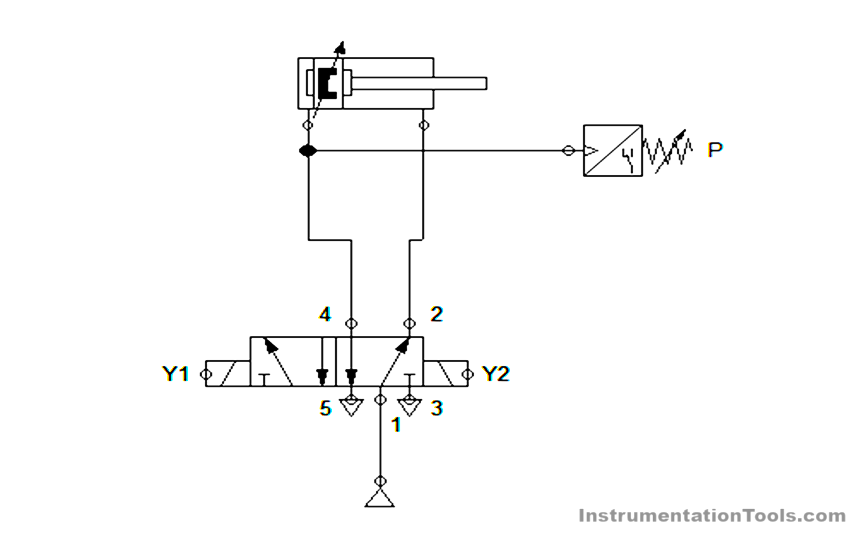
Pneumatic Circuit

electro pneumatic circuit

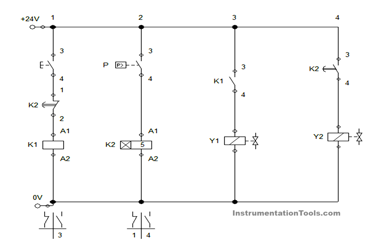
Electric Circuit

pneumatic cylinder with timer

Circuit Principle

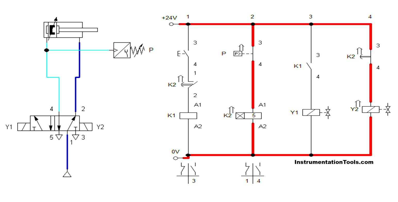
  • In a pneumatic circuit, an operating pressure of 6 bar is given to the system through the compressor
  • The output supply from the compressor is given to the 5/2 Direction control valve, which is connected to the double-acting cylinder. During that connection cylinder was in home position. And the Pressure sensor was connected to the extend stroke connection of the cylinder.
  • In an electric circuit, power supply of 24V DC is used. Thus, the whole system was operated with the 24V only.
  • Once the start button is pressed, the relay K1 is activated, which activates the solenoid coil Y1. The activation of solenoid Y1 makes the cylinder to move forward.
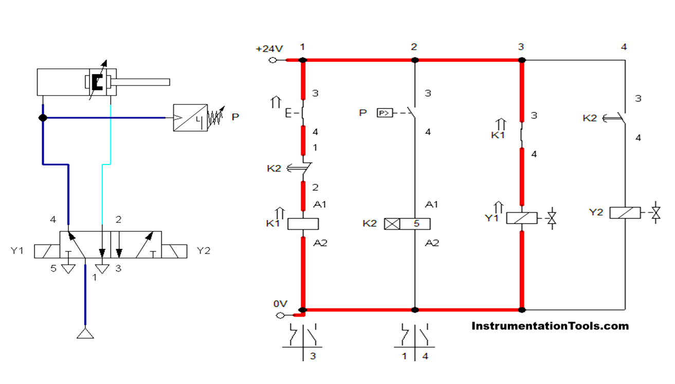
timer relay in pneumatic circuit
  • Since the cylinder was extended forward, the pressure will be in the extended port where the pressure sensor was connected.
  • In the pressure sensor, the switching pressure of 5 bar is fixed. Since the switching pressure is less than the operating pressure, the pressure sensor connection was activated in the electrical circuit.
  • Activation of the pressure sensor causes the timer to activate. On-delay time of 5 second was set on the timer. Once the 5 seconds were completed on the timer, the timer connection makes the solenoid Y2 activate by breaking the connection of relay coil K1 and solenoid coil Y1.
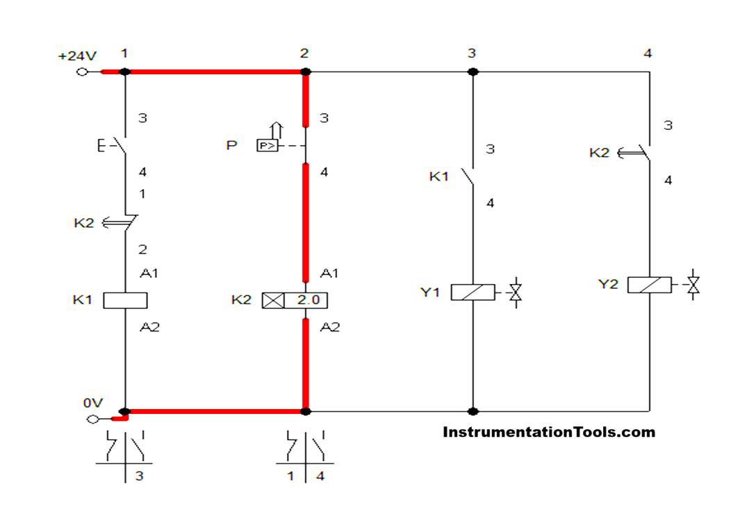
electro-pneumatic relay logic
  •  Activation of solenoid coil Y2 causes the cylinder to retract and makes the cycle complete. Thus, the cylinder reaches its home position, and the process will continue after pressing the start button.
pressure sensor pneumatic control
  • One important factor in the circuit is, if the switching pressure in the pressure sensor is above the main air supply means it will not activate. So we need to check this while designing the circuit.

Conclusion

Thus, these types of control systems were used in industrial applications where exact timing and pressure-dependent operations were needed. For that, we are controlling the retraction motion of the cylinder with the condition of pressure and time. So, as per the requirement, the process will be done safely, reliably, and accurately in industrial automation processes.

Read Next:

  • What is a Pneumatic Cylinder?
  • Pneumatic Valves and Cylinders Sizing
  • Sequential PLC Program Pneumatic Valve
  • Control of Pneumatic Cylinder and Motor
  • Master & Slave Cylinder Operation

Don't Miss Our Updates
Be the first to get exclusive content straight to your email.
We promise not to spam you. You can unsubscribe at any time.
Invalid email address
You've successfully subscribed !

Continue Reading

What is Fuzzy Logic? Advantages, Disadvantages, Applications
Working of Air Compressor – Types – Control Techniques
Intrinsic Safety of Instruments
The Dorm Room Essentials And Why You Need Them
Common Materials used in Instrumentation Cables
What is a Viscometer? – Types, Applications, Advantages
Share This Article
Facebook Whatsapp Whatsapp LinkedIn Copy Link
Share
Leave a Comment

Leave a Reply Cancel reply

Your email address will not be published. Required fields are marked *

Stay Connected

128.3kFollowersLike
69.1kFollowersFollow
210kSubscribersSubscribe
38kFollowersFollow

Categories

Explore More

What is Transparent Solar Panel? – Working Principle and Theory
Laser Doppler Anemometer
Field Instrumentation Tips
Difference Between Predictive Maintenance and Preventive Maintenance
Everything You Need to Know About Ceramic Bearings
Introduction to Digital Systems
How to Choose the Best Tungsten Grinders for Welders?
HVAC Valves

Keep Learning

Look Listen Feel of Instruments

Look Listen Feel of Instruments – Instrumentation Engineer Maintenance

What is IO-Link in Smart Manufacturing

What is IO-Link in Smart Manufacturing?

2 wire transmitter current loops

2-wire Transmitters Current Loops

Applications of CNC Machining

Important Applications of Rapid Prototype CNC Machining Services

CNC Milling versus CNC Turning

CNC Milling versus CNC Turning – Which is the Best Option?

Automation in Agriculture

Automation in Farming & Agriculture

Industrial IoT Job Roles and Responsibilities

IoT Engineer Job Roles and Responsibilities

What is a Load Cell

What is a Load Cell ?

Learn More

Power Systems Questions & Answers

Power Systems MCQ Series 12

Ion Spectrometers Questions & Answers

Instrumentation for Electron Spectroscopy

Digital Control Systems

Spectrum Analysis of Sampling Process

Power Electronics Objective Questions

Power Electronics Applications Objective Questions

Voltage Polarities

Voltage Polarity and Current Direction

Process Control System

Basics of Process Control Systems

Differential Pressure versus Flow Rate

Orifice Flowmeter Rangeability

PV Tracking in PID Controllers

What is PV Tracking ?

Menu

  • About
  • Privacy Policy
  • Copyright

Quick Links

  • Learn PLC
  • Helping Hand
  • Part Time Job

YouTube Subscribe

Follow US
All rights reserved. Reproduction in whole or in part without written permission is prohibited.
Welcome Back!

Sign in to your account

Username or Email Address
Password

Lost your password?