Inst ToolsInst ToolsInst Tools
  • Courses
  • Automation
    • PLC
    • Control System
    • Safety System
    • Communication
    • Fire & Gas System
  • Instrumentation
    • Design
    • Pressure
    • Temperature
    • Flow
    • Level
    • Vibration
    • Analyzer
    • Control Valve
    • Switch
    • Calibration
    • Erection & Commissioning
  • Interview
    • Instrumentation
    • Electrical
    • Electronics
    • Practical
  • Q&A
    • Instrumentation
    • Control System
    • Electrical
    • Electronics
    • Analog Electronics
    • Digital Electronics
    • Power Electronics
    • Microprocessor
  • Request
Search
  • Books
  • Software
  • Projects
  • Process
  • Tools
  • Basics
  • Formula
  • Power Plant
  • Root Cause Analysis
  • Electrical Basics
  • Animation
  • Standards
  • 4-20 mA Course
  • Siemens PLC Course
Reading: Label the Electrical Circuit Schematic
Share
Font ResizerAa
Inst ToolsInst Tools
Font ResizerAa
  • Courses
  • Design
  • PLC
  • Interview
  • Control System
Search
  • Courses
  • Automation
    • PLC
    • Control System
    • Safety System
    • Communication
    • Fire & Gas System
  • Instrumentation
    • Design
    • Pressure
    • Temperature
    • Flow
    • Level
    • Vibration
    • Analyzer
    • Control Valve
    • Switch
    • Calibration
    • Erection & Commissioning
  • Interview
    • Instrumentation
    • Electrical
    • Electronics
    • Practical
  • Q&A
    • Instrumentation
    • Control System
    • Electrical
    • Electronics
    • Analog Electronics
    • Digital Electronics
    • Power Electronics
    • Microprocessor
  • Request
Follow US
All rights reserved. Reproduction in whole or in part without written permission is prohibited.
Inst Tools > Blog > Animation > Label the Electrical Circuit Schematic

Label the Electrical Circuit Schematic

Last updated: March 4, 2021 11:26 am
Editorial Staff
Animation Control Systems PLC Tutorials
No Comments
Share
1 Min Read
SHARE

Here we give you the basic full-wave bridge rectifier to identify the electronic components in the circuit. Next, you have to identify the labels in the electrical circuit schematic.

Contents
Electrical Circuit Label SchematicSTART

Drag the letter that corresponds with the schematic label, drop it into the colored circle next to the correct symbol.

Electrical Circuit Label Schematic

Electrical Circuit Label Schematic Quiz

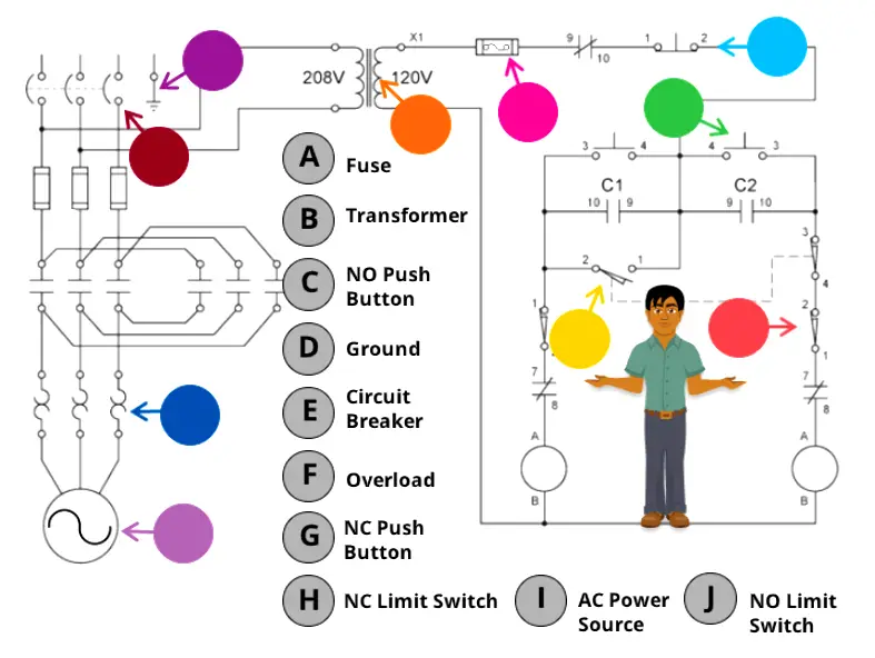
You have to drag and drop the correct technical words to the respective circle.

Requirements: Desktop or Laptop

Click on the below start button to launch the schematic.

START

Also Check: Online Simulations

If you liked this article, then please subscribe to our YouTube Channel for PLC and SCADA video tutorials.

You can also follow us on Facebook and Twitter to receive daily updates.

Don't Miss Our Updates
Be the first to get exclusive content straight to your email.
We promise not to spam you. You can unsubscribe at any time.
Invalid email address
You've successfully subscribed !

Continue Reading

PLC Code to Start & Stop Motor and Pump as per Logic
How to Create a Project in LabVIEW?
Introduction to SCADA
Ratio Controller Example
SCADA for Substation Automation
Feedforward Vs Feedback Control
Share This Article
Facebook Whatsapp Whatsapp LinkedIn Copy Link
Share
Leave a Comment

Leave a Reply Cancel reply

Your email address will not be published. Required fields are marked *

Stay Connected

128.3kFollowersLike
69.1kFollowersFollow
210kSubscribersSubscribe
38kFollowersFollow

Categories

Explore More

Tank Level Control in PLC
Motor Speed Control using VFD and PLC Programming
Design a Water Pump PLC Program using CX-Programmer
Free Schneider PLC Training – Automation Course
Automatic Motor Forward and Reverse Control using Timer
Building Management System
Siemens PLC Mathematics Instructions
100 PLC Quiz Questions : True or False

Keep Learning

PLC Best Practices

#1 PLC Best Practices – Split PLC Code into Modules

PLC Memory Organization - Data Files and Program Files

PLC Memory Organization – Data Files and Program Files

Sequential Timer Control of Lamps

Schneider PLC Example: Control Lamps Sequences

Micro 870 Rockwell PLC

Rockwell Automation Allen Bradley PLC for Smaller and Medium Projects

Configure Analog Inputs and Outputs in Delta PLC

How to Configure Analog Inputs and Outputs in Delta PLC?

Control System Vendor Internal Test Procedures

Vendor View of Supplying Industrial Process Control & Safety Systems

PLC Example on Switch Program with Timers

PLC Example on Switch Program with Timers

Valve Diaphragm Actuator

Spring and Diaphragm Pneumatic Actuators

Learn More

Pressure Measurement Objective Questions

Pressure Measurement Objective Questions

Effluent Treatment Plant

Basic Components of Effluent Treatment Plant (ETP)

Software Troubleshooting Errors and Faults in Siemens PLC

Software Troubleshooting Errors and Faults in Siemens PLC

PLC PID tuning parameters

Programming and Tuning PID Controller in PLC – Siemens TIA Portal

PLC Programming for Pumping and Draining System

PLC Programming for Pumping and Draining System

Unbonded Strain Gauge Principle

Unbonded Strain Gauge Principle

PLC to PLC Communication using S7 Connection

PLC to PLC Communication using S7 Connection PUT & GET Instructions

SIS Audit & Assessment - Safety Instrumented System

SIS Audit & Assessment – Safety Instrumented System

Menu

  • About
  • Privacy Policy
  • Copyright

Quick Links

  • Learn PLC
  • Helping Hand
  • Part Time Job

YouTube Subscribe

Follow US
All rights reserved. Reproduction in whole or in part without written permission is prohibited.
Welcome Back!

Sign in to your account

Username or Email Address
Password

Lost your password?