Drive multiple speeds with different reference. Write PLC program for drive multiple speeds with different reference.
PLC Multiple Speed Reference
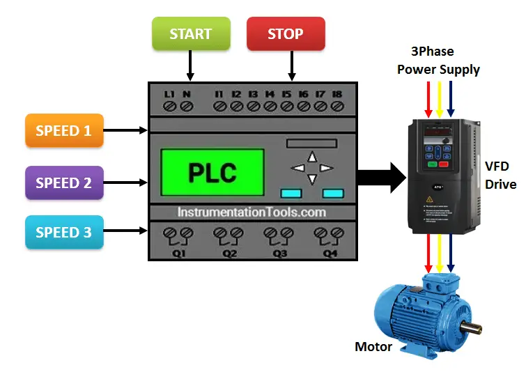
In drive application we need to operate drive in multiple speeds using different speed reference. This function is possible using PLC. For example here there is one drive and it needs to be operated with different speed reference. We will operate drive with three different speeds.
Consider three reference buttons which can select speed as per requirement. First select momentary button so drive reference will be moved in analog reference of the drive. When reference is moved and start button is pressed, drive will run as per the moved speed.
List of Inputs/Outputs
List of Inputs
- Start PB :- I1
- Stop PB :- I2
List of Outputs
- Motor :- Q1
List of register
- Register A :- Analog reference for drive
- Memory coil 1 :-Speed 1
- Memory coil 2 :-Speed 2
- Memory coil 3 :-Speed 3
PLC Ladder programming explanation
NETWORK 1 :
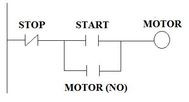
Motor START/STOP logic is used to operate motor. Also latching circuit is used for latching.
NETWORK 2 :

Move instruction is used for first speed reference. If speed 1 button is pressed form SCADA or HMI, drive will run as per given speed.
NETWORK 3 :

Move instruction is used for first speed reference. If speed 2 button is pressed form SCADA or HMI, drive will run as per given speed.
NETWORK 4 :

Move instruction is used for first speed reference. If speed 3 button is pressed form SCADA or HMI, drive will run as per given speed. .
NETWORK 5 :
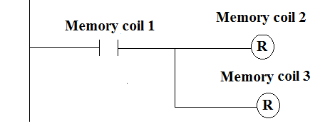
Reset logic is used for interlocking (for Speed Reference 1).
NETWORK 6 :
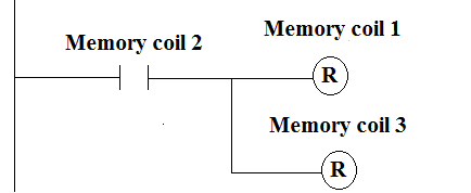
Reset logic is used for interlocking (for Speed Reference 2).
NETWORK 7 :
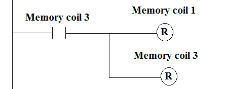
Reset logic is used for interlocking (for Speed Reference 3).
If you liked this article, then please subscribe to our YouTube Channel for PLC and SCADA video tutorials.
You can also follow us on Facebook and Twitter to receive daily updates.
Read Next:
Boolean Algebra Equivalent PLC Logic
Boiler Start-up PLC Logic Control
Sub-routines Instructions in PLC





This site is very good in eDucating with plc
Very useful thank you so much for your great efforts