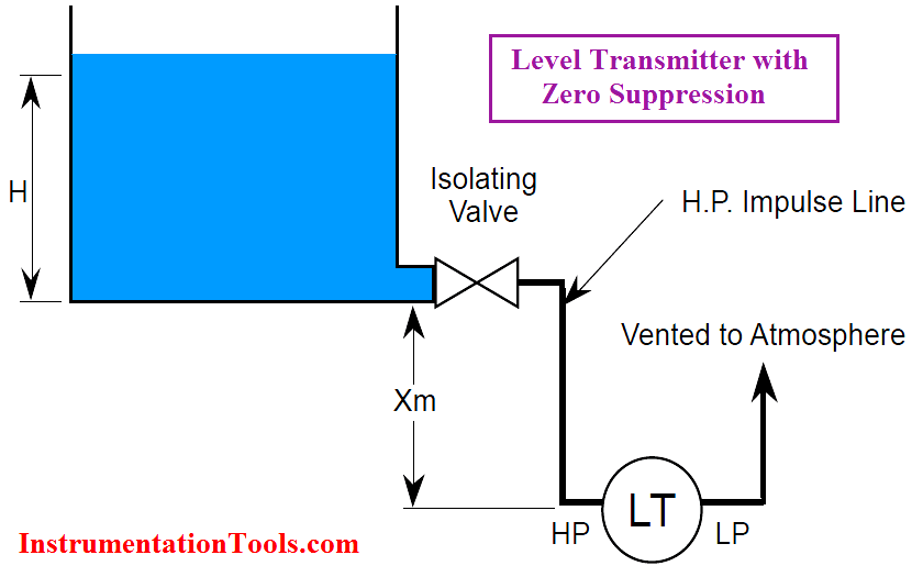
It would be idealistic to say that the DP Level Transmitters can always be located at the exact the bottom of the vessel where we are measuring fluid level in. Hence, the measuring system has to consider the hydrostatic pressure of the fluid in the sensing lines themselves. This leads to two compensations required.
Zero Suppression
In some cases, it is not possible to mount the level transmitter right at the base level of the tank. Say for maintenance purposes, the level transmitter has to be mounted X meters below the base of an open tank as shown in below figure.

The liquid in the tank exerts a varying pressure that is proportional to its level H on the high-pressure side of the transmitter. The liquid in the high pressure impulse line also exerts a pressure on the high-pressure side. However, this pressure is a constant (P = S – X) and is present at all times. When the liquid level is at H meters, pressure on the high-pressure side of the transmitter will be:
Phigh = S⋅H + S⋅ X + Patm
Plow = Patm
ΔP = Phigh – Plow = S⋅H + S⋅ X
That is, the pressure on the high-pressure side is always higher than the actual pressure exerted by the liquid column in the tank (by a value of S⋅ X). This constant pressure would cause an output signal that is higher than 4 mA when the tank is empty and above 20 mA when it is full. The transmitter has to be negatively biased by a value of -S⋅ X so that the output of the transmitter is proportional to the tank level (S⋅H) only. This procedure is called Zero Suppression and it can be done during calibration of the transmitter.
Zero Elevation
When a wet leg installation is used (see below Figure), the low-pressure side of the level transmitter will always experience a higher pressure than the high-pressure side. This is due to the fact that the height of the wet leg (X) is always equal to or greater than the maximum height of the liquid column (H) inside the tank.
When the liquid level is at H meters, we have:
Phigh = Pgas + S⋅H
Plow = Pgas + S⋅ X
ΔP = Phigh – Plow = S⋅H – S⋅ X = – S (X – H)
The differential pressure ΔP sensed by the transmitter is always a negative number (i.e., low pressure side is at a higher pressure than high pressure side). ΔP increases from P = -S⋅ X to P = -S (X-H) as the tank level rises from 0% to 100%.
If the transmitter were not calibrated for this constant negative error (-S⋅ X), the transmitter output would read low at all times.
To properly calibrate the transmitter, a positive bias (+S⋅ X) is needed to elevate the transmitter output.
This positive biasing technique is called zero elevation.
The conveyor sorting machine is widely used in the packing industries using the PLC program…
Learn the example of flip-flop PLC program for lamps application using the ladder logic to…
In this article, you will learn the STAR DELTA programming using PLC controller to start…
Lube oil consoles of rotary equipment packages in industrial process plants are usually equipped with…
Rotating equipment packages such as pumps, compressors, turbines need the lube oil consoles for their…
This article explains how to blink lights in ladder logic with a detailed explanation video…
View Comments
hai
this is very useful for all instrument guys ur way of presentation would be appreciate keep on always
thanks
Sir,
I had referred modules of level transmitter & i can't understand a particular line that "LP side posses higher pressure higher than HP side", then how can we say that side as low pressure side.
Ya well I got it.