Inst ToolsInst ToolsInst Tools
  • Courses
  • Automation
    • PLC
    • Control System
    • Safety System
    • Communication
    • Fire & Gas System
  • Instrumentation
    • Design
    • Pressure
    • Temperature
    • Flow
    • Level
    • Vibration
    • Analyzer
    • Control Valve
    • Switch
    • Calibration
    • Erection & Commissioning
  • Interview
    • Instrumentation
    • Electrical
    • Electronics
    • Practical
  • Q&A
    • Instrumentation
    • Control System
    • Electrical
    • Electronics
    • Analog Electronics
    • Digital Electronics
    • Power Electronics
    • Microprocessor
  • Request
Search
  • Books
  • Software
  • Projects
  • Process
  • Tools
  • Basics
  • Formula
  • Power Plant
  • Root Cause Analysis
  • Electrical Basics
  • Animation
  • Standards
  • 4-20 mA Course
  • Siemens PLC Course
Reading: Down Counter PLC Program
Share
Font ResizerAa
Inst ToolsInst Tools
Font ResizerAa
  • Courses
  • Design
  • PLC
  • Interview
  • Control System
Search
  • Courses
  • Automation
    • PLC
    • Control System
    • Safety System
    • Communication
    • Fire & Gas System
  • Instrumentation
    • Design
    • Pressure
    • Temperature
    • Flow
    • Level
    • Vibration
    • Analyzer
    • Control Valve
    • Switch
    • Calibration
    • Erection & Commissioning
  • Interview
    • Instrumentation
    • Electrical
    • Electronics
    • Practical
  • Q&A
    • Instrumentation
    • Control System
    • Electrical
    • Electronics
    • Analog Electronics
    • Digital Electronics
    • Power Electronics
    • Microprocessor
  • Request
Follow US
All rights reserved. Reproduction in whole or in part without written permission is prohibited.
Inst Tools > Blog > PLC Tutorials > Down Counter PLC Program

Down Counter PLC Program

Last updated: March 4, 2021 3:26 pm
Editorial Staff
PLC Tutorials
1 Comment
Share
4 Min Read
SHARE

To study the working of Up Counter PLC program in Allen Bradley Programmable Logic Controller (PLC).

Contents
Down CounterDown Counter Description Using PLC ProgramCounter Count Down Bit (C5:0/DN)Counter Count Down Bit (C5:0/CD):Counter Under Flow Bit (C5:0/UN):

Down Counter

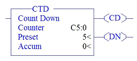
Down Counter (CTD) Instruction

In the above picture, there are totally three parameter,

COUNTER: C4:0 – Counter File name (TimerC5:0, C5:1,C5:2…)

PRESET – PRE : Limit value of COUNT-Up to how much it should count

ACCUMULATOR – ACC : Running Value of counter when condition turn ON.
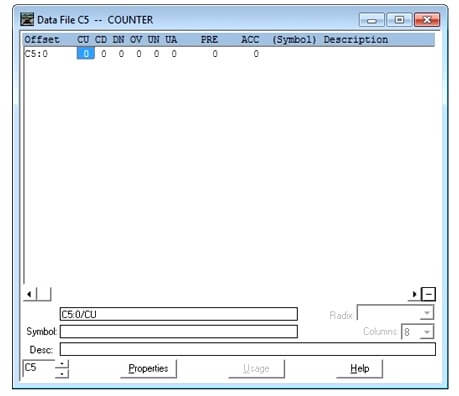
Down Counter Data File

From the data file,along with preset and accumulator, we have few more bits,

CD: Countdown Bit-whenever the counter is enable makes this bit to go ON.

DN: Done Bit-When accumulator value equals preset value, done bit turns to ON.

UA: Counter Underflow – When accumulator value reached the limit value (-32767),it rolls back to +32767 for the upcoming counter operation, underflow bit turns ON, in this condition.

Notes:

UA – Update Accumulator Value-Only used when high speed counters are used in the program.

CU & OV – Used for Up Counter Function.

Down Counter Description Using PLC Program

I:0/0 is used to give input to counter and Preset value and accumulator value set to 5.

Counter Count Down Bit (C5:0/DN)

In the below Ladder logic,

Rung 0000

Having condition input I:0/0 which gives input to counter to perform counter down function.

Rung 0001

Having Counter CU Bit which enable only when counter is in function or when input to the counter turns ON and accumulator value counted down.

Rung 0002

Counter done bit turns on when accumulator value equals preset value.
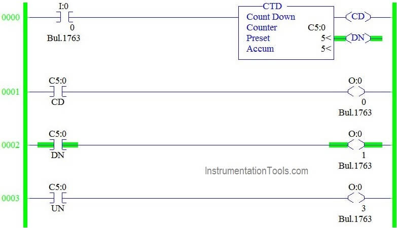
Counter Count Down Bit

Counter Count Down Bit (C5:0/CD):

In the below Ladder logic,

Rung 0000

Having condition input I:0/0 which gives input to counter to perform counter function.

Rung 0001

Having Counter CU Bit which enable only when counter is in function or when input to the counter turns ON and accumulator value counted down.
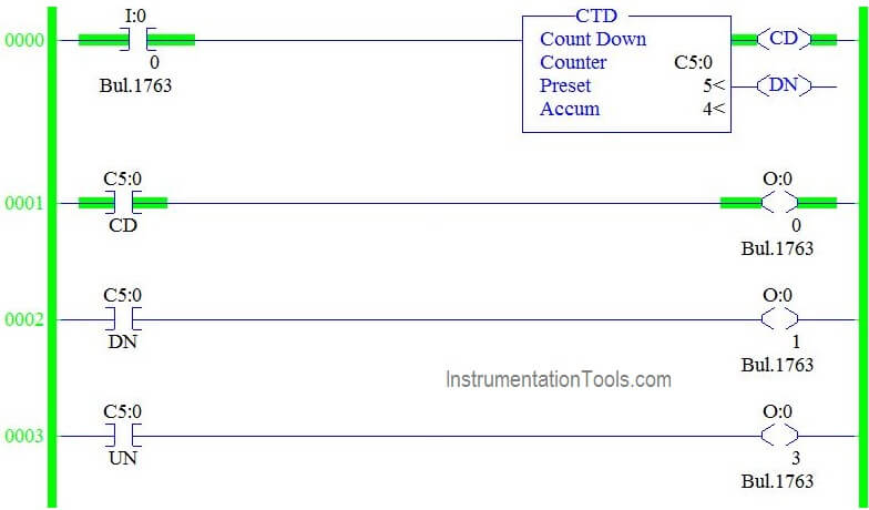
Down Counter PLC Programming

In the below Ladder logic,

Rung 0000

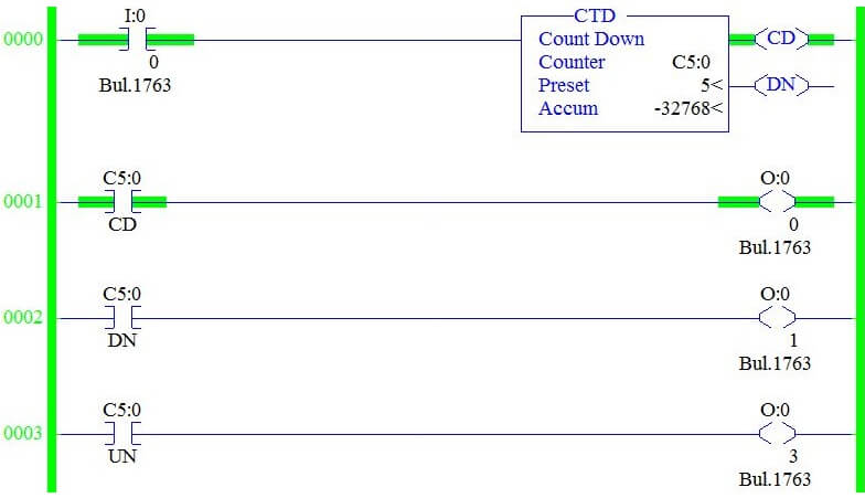
Having condition input I:0/0 which gives input to counter to perform counter function. Accumulator value goes to negative if I:0/0 goes ON for 6th time in the below case,
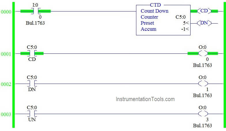
Down Counter Ladder Logic

Counter Under Flow Bit (C5:0/UN):

In the Below Ladder Logic,

Counter accumulator value under flows when accumulator value reaches -32767 in Allen Bradley PLC Programming.
plc counter programming examples

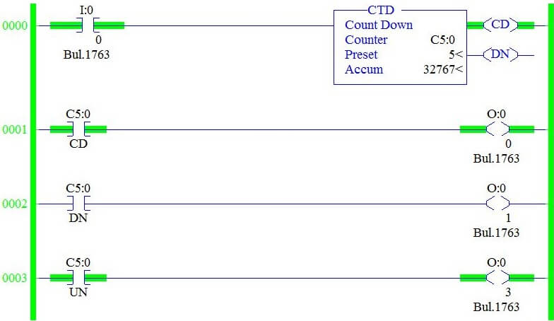
In the below ladder Logic,

When we turn ON the I:0/0 ,accumulator value rolls back to 32768 and start counting down from 32767 to -32767.Counter underflow bit turns ON when this condition happen (Rung 003).
How to Use Counters in PLC Programming

Conclusion:

We can use this explanation to understand the working of Down Counter function in Allen Bradley Programmable Logic Controller (PLC).

Author :Ā Hema Sundaresan

If you liked this article, then please subscribe to our YouTube Channel for PLC and SCADA video tutorials.

You can also follow us on Facebook and Twitter to receive daily updates.

Read Next:
Industrial Control Systems

What is SCADA System ?

PLC Tanks Filling Logic

Move Instruction in PLC

PLC Hardware Parts

Don't Miss Our Updates
Be the first to get exclusive content straight to your email.
We promise not to spam you. You can unsubscribe at any time.
Invalid email address
You've successfully subscribed !

Continue Reading

Remote Factory Acceptance Test
#2 PLC Best Practices – Track Operating Modes
PLC Interview Questions and Answers
Count the Number of Cartons in a Storage Area PLC Logic
Converter Instruction in Siemens PLC Programming
What is Complementary Split Range Control (CSRC)?
Share This Article
Facebook Whatsapp Whatsapp LinkedIn Copy Link
Share
1 Comment
  • Toluwani says:
    October 1, 2021 at 12:18 am

    Hello Hema,
    Please, is there a way to hinder the countdown of the counter from reaching the negative count values without using a limits or comparison instructions?

    Reply

Leave a Reply Cancel reply

Your email address will not be published. Required fields are marked *

Stay Connected

128.3kFollowersLike
69.1kFollowersFollow
210kSubscribersSubscribe
38kFollowersFollow

Categories

Explore More

PLC Problems Troubleshooting
How to Create Faceplate in FactoryTalk View Studio?
Failsafe Wiring Practices
Standard Colors in PLC Automation Systems
PLC Math instructions
How to Backup and Restore from Simatic Prosave HMI?
PLC Program for Ceramic Burning Oven Conveyor System
How to use JUMP Instruction in PLC Ladder Logic?

Keep Learning

Steps in PLC System Design

Steps in PLC System Design

Motor Feedback Fail Logic in PLC

Motor Feedback Fail Logic in PLC

Code Simulation of Safety Circuit

Feedback Monitoring in Safety PLC

PLC Program for motor operation based on time cycle

PLC Motor Operation based on Time Cycle Sequence – Program

Batch MixingĀ withĀ PLC Ladder Logic Program

Batch MixingĀ withĀ PLC Ladder Logic Program

Industrial PLC Communication Network

Basics of Industrial Communication Networks

PLC Control Panel

Inside the PLC Control Panel: How Much Do You Know?

RSLogix 5000 PLC Programming Procedure

Learn More

What is a Pilot Valve?

What is a Pilot Valve? When do we use a Pilot Valve?

Unstable & Drifting Values of Differential Pressure Transmitter

Unstable & Drifting Values of Differential Pressure Transmitter Problem

Pressure instruments example circuit

Motion-Balance and Force-Balance Instruments

ball Valve Animation

Basics of Ball Valves

What is Open Telemetry?

What is Open Telemetry? – Principles and Benefits

Digital Control Systems

Z-transform Analysis of Sampled-Data Control Systems

Motor Operated Valve Problems and Troubleshooting

Motor Operated Valve Problems and Troubleshooting

Rupture disks

Rupture disks

Menu

  • About
  • Privacy Policy
  • Copyright

Quick Links

  • Learn PLC
  • Helping Hand
  • Part Time Job

YouTube Subscribe

Follow US
All rights reserved. Reproduction in whole or in part without written permission is prohibited.
Welcome Back!

Sign in to your account

Username or Email Address
Password

Lost your password?