The DOL and RDOL are motor starters used to control the power supply to the motor.
The DOL starter controls the motor power ON or OFF and motor rotates in one direction only whereas the RDOL starter can make the motor to rotate in clockwise and anti-clockwise directions with two START buttons and one STOP button.
In RDOL, one START button is used to run the motor in clockwise direction and another START button to run the motor in anti-clockwise direction. The STOP button is common for both directions.
What is DOL Starter?
The Direct OnLine starter is a simple motor control device which is used to provide the power supply to the motor with a basic protection & control circuit.
When we power the industrial motors, it results in a heavy rush of the current of the order of six to eight times the normal full load current drawn by the motors.
The high current rapidly decreases as the motor picks up speed but it is at a very low power factor and thus tends to disturb the voltage of the supply in the distribution lines. For this reason, this type of starter is limited to the motor up to 5 HP rating.
A direct online starter essentially consists of a contactor having four normally open (NO) and an OFF contact which are used to start and stop the motor.
To protect against overload, thermal or magnetic over-load coils are connected in each phase. (overload relay)
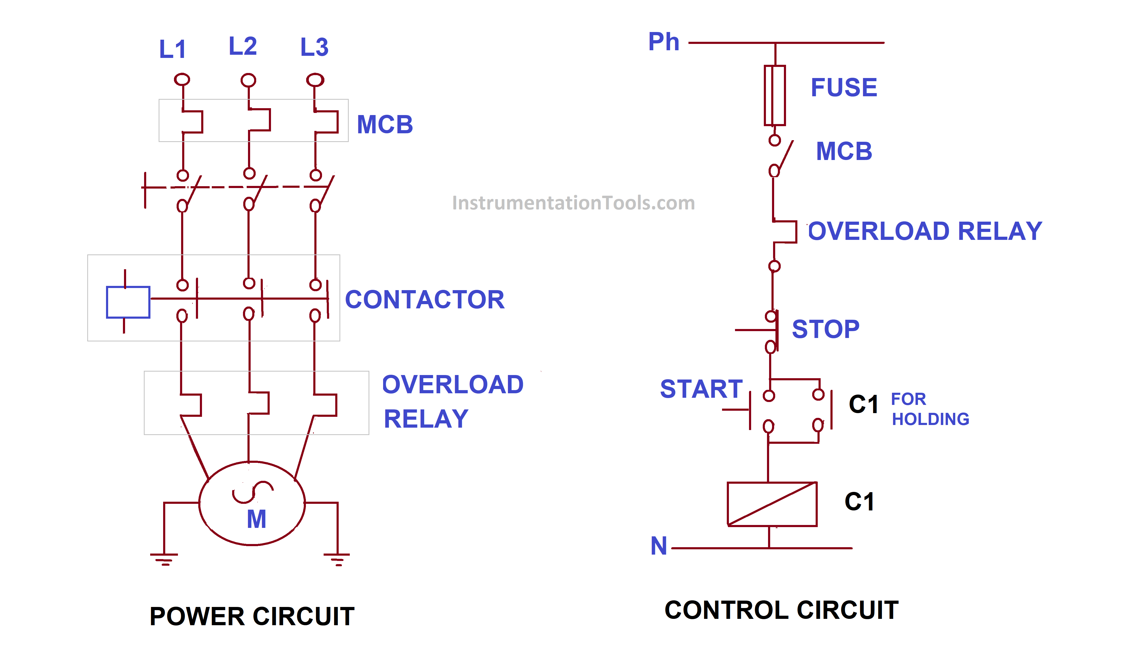
DOL Starter working Principle
To start the motor, the ON push button (green) is pressed which energies the no-volt coil by connecting it across the two phases.
The no-volt coil pickups its plunger in such a direction that all the normally open (NO) contacts are closed and the motor is connected across the power supply through three contacts.
The fourth contact (NO) serves as a hold-on contact which keeps the no-volt coil circuit closed even after the ON push button is released. (latching circuit)
To stop the motor, the OFF push button (red) is pressed momentarily which de-energies the no-volt coil opening the main contacts which disconnects the power to the motor.
When the motor is overloaded, the thermal overload relay contact, connected to the control circuit opens thus disconnecting the no-volt relay from the supply.
Overload protection is accomplished by thermal element overload relay.
Components of Motor Starters
1) Contactor
A contactor is a heavy-duty relay with a high current rating used to power up an electrical motor. The current rating for contactor range from 10 amps to several hundred amps.
Overload protection is provided along with the contractors to start the motor.
2) Overload relay (overload protection)
Most motor winding failure occurs due to overload. Motor overload tends to the heating of motor winding which results in the weakening of winding insulation.
A small amount of overload does not lead to a motor failure immediately but it will eventually shorten the expected lifetime
3) Miniature circuit breaker (MCB)
To protect the motor from short circuit conditions and avoid damage to motor winding MCB is used in the DOL circuit.
4) Push buttons
There are two pushbuttons are used in dol motor starter.
One is a green color for the start button and the other is red for the stop push button.
Start push button
This push button needs to press and supply gets applied to the motor through a power contactor.
Stop push button
This is NC type push button we need to press to stop the motor from running condition after pressing the stop button contactor coil gets de-energized with the opening of contacts.
Due to this switching motor in operation gets disconnected from the supply and the motor stops rotating.
Reverse DOL Starter (RDOL)
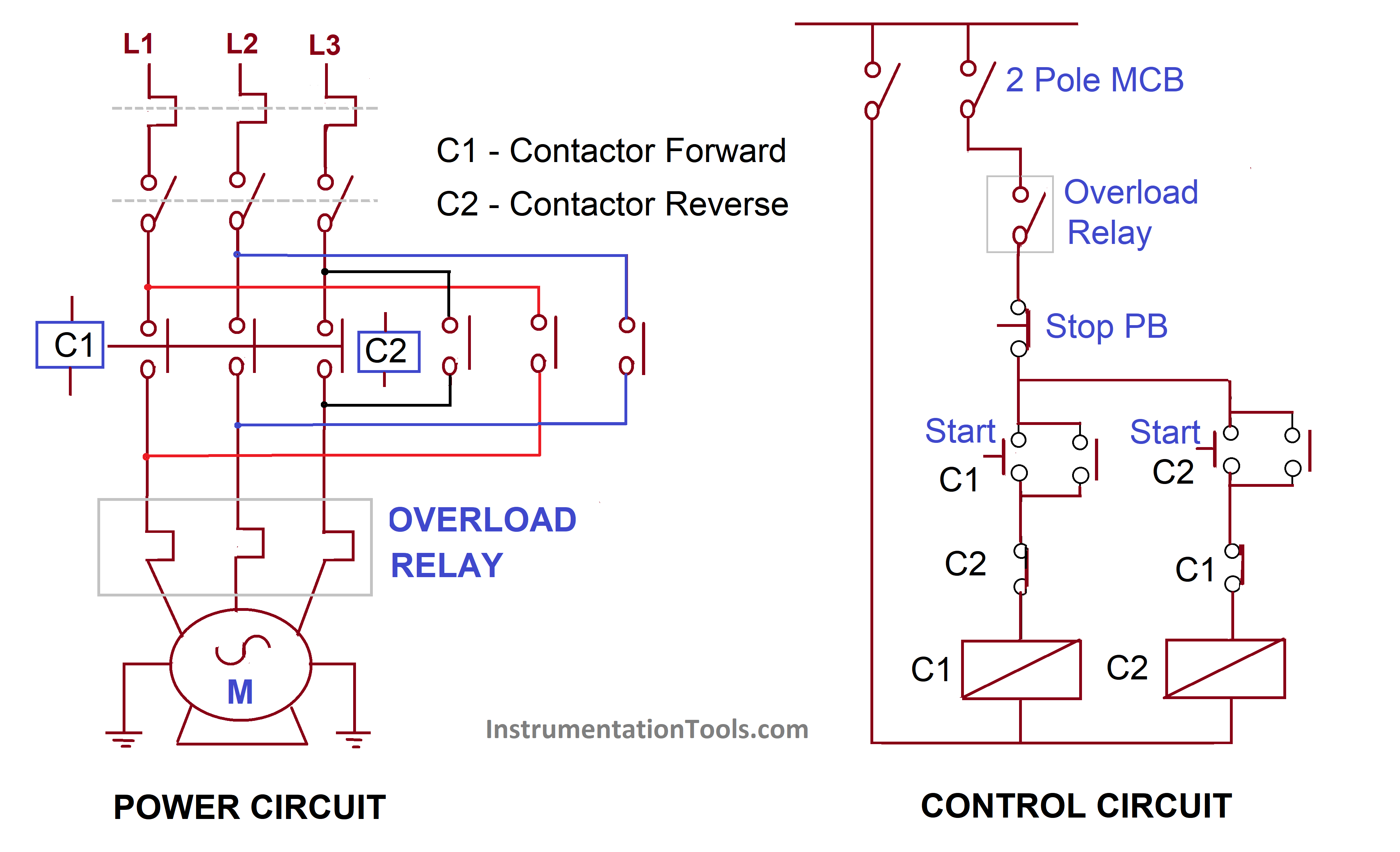
Reverse Direct OnLine starter (RDOL starter) consists of two contactors connecting the power supply to the Motor.
The first contactor provides a phase sequence to the stator of the motor to produce rotation in one direction, while another contactor has a different phase sequence changing the direction of rotation of the motor.
The two contactors are complementary to each other and can be used to reverse the direction of the motor.
An RDOL reversing starter can connect to the motor for rotation in either direction. Such a starter contains two DOL circuits – one for clockwise operation and the other for counter-clockwise operation, with mechanical and electrical interlocks to avoid closure at the same time.
For three-phase motors, this is achieved by changing the wires connecting across any two phases. Single-phase AC motors and direct-current motors require extra other devices for reversing rotation.
Also Read: Start Delta Starter
Advantages of DOL and RDOL Starters
- RDOL starter is simply two DOL starters in a single box.
- Direct On-Line motor starter is the economical motor starter and only for one direction is desired.
- With a Reverse DOL starter, both forward and reverse rotation can be accomplished.
- DOL starters do not require special arrangements for starting the motor.
- Used for smaller motors driving small loads as there is not a large quantity of torque and resistance.
- DOL is the simple control circuitry motor starter, less space is needed.
- Used up to 5HP motors, not good for larger motors and loads.
Disadvantages of DOL and RDOL Starters
- 100% line voltage is applied to the starter, high current stress is applied on motor winding.
- Particularly for a Reverse DOL starter, some extra space is needed to accommodate the hardware.
- DOL or RDOL starter is not suitable for high rating motor.
- High starting torque
Applications of DOL and Reverse DOL Starters
- Particularly, RDOL starter is used for conveyor belts, which often require movement on both sides.
- Used in where a high starting inrush current does not cause damage to an induction motor.
- Used for 3 phase induction motor is low power rating up to 5 HP.
- Helpful where a high starting current does not cause an excessive voltage drop in the supply circuit.
Read Next:


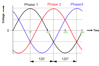

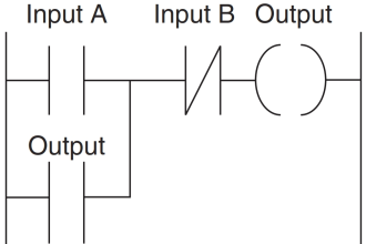


diagram of power circuit is wrong for reverse dol starter. and is it write please explain me
Power circuit for RDOL is wrong here.
Please, check & correct.
Any two phase should be interchanged to make it correct. (Other one will be as it is).