Inst ToolsInst ToolsInst Tools
  • Courses
  • Automation
    • PLC
    • Control System
    • Safety System
    • Communication
    • Fire & Gas System
  • Instrumentation
    • Design
    • Pressure
    • Temperature
    • Flow
    • Level
    • Vibration
    • Analyzer
    • Control Valve
    • Switch
    • Calibration
    • Erection & Commissioning
  • Interview
    • Instrumentation
    • Electrical
    • Electronics
    • Practical
  • Q&A
    • Instrumentation
    • Control System
    • Electrical
    • Electronics
    • Analog Electronics
    • Digital Electronics
    • Power Electronics
    • Microprocessor
  • Request
Search
  • Books
  • Software
  • Projects
  • Process
  • Tools
  • Basics
  • Formula
  • Power Plant
  • Root Cause Analysis
  • Electrical Basics
  • Animation
  • Standards
  • 4-20 mA Course
  • Siemens PLC Course
Reading: Differential Pressure Transmitter Questions
Share
Font ResizerAa
Inst ToolsInst Tools
Font ResizerAa
  • Courses
  • Design
  • PLC
  • Interview
  • Control System
Search
  • Courses
  • Automation
    • PLC
    • Control System
    • Safety System
    • Communication
    • Fire & Gas System
  • Instrumentation
    • Design
    • Pressure
    • Temperature
    • Flow
    • Level
    • Vibration
    • Analyzer
    • Control Valve
    • Switch
    • Calibration
    • Erection & Commissioning
  • Interview
    • Instrumentation
    • Electrical
    • Electronics
    • Practical
  • Q&A
    • Instrumentation
    • Control System
    • Electrical
    • Electronics
    • Analog Electronics
    • Digital Electronics
    • Power Electronics
    • Microprocessor
  • Request
Follow US
All rights reserved. Reproduction in whole or in part without written permission is prohibited.
Inst Tools > Blog > Pressure Measurement > Differential Pressure Transmitter Questions

Differential Pressure Transmitter Questions

Last updated: January 11, 2020 6:52 pm
Editorial Staff
Pressure Measurement
2 Comments
Share
2 Min Read
SHARE

Connect a loop-powered differential pressure transmitter to a DC voltage source, a milliammeter, a 250 ohm resistor, and a diode as shown in the below figure.

Differential Pressure Transmitter

Differential Pressure Transmitter Question


Schematic Diagram

The schematic diagram shows the above figure connections in the circuit form.

2 wire Transmitter Schematic

We power-up the transmitter and it is now functioning, answer the following questions:

Question 1:

Trace the direction of current through this DC circuit (using conventional flow notation) and identify the polarity of the voltage across each component in accordance with that component’s function as either an electrical source or an electrical load.

Question 2:

Explain how to measure the transmitter’s output signal three different ways:

  • Measuring a voltage drop across the 250 resistor (1-5 V signal)
  • Breaking the circuit to directly measure current with a milliammeter (4-20 mA signal)
  • Connecting a milliammeter in parallel with the diode (4-20 mA signal)

Question 3:

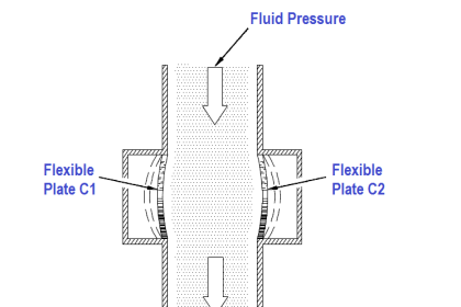
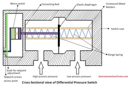
How does an applied pressure (blowing into the plastic tube) to the “High” pressure port on the transmitter affect the electrical signal? How about an applied pressure to the “Low” pressure port?

Question 4:

While measuring current (with the milliammeter shorting across the diode), temporarily short past the 250 ohm resistor with a jumper wire. How does this affect the circuit current, and why?

Question 5:

How would the pressure transmitter respond if equal pressures were applied to both “H” and “L” ports?

Question 6:

One of the basic rules students learn when first using their multimeters is never connect an ammeter in parallel with anything, only in series. Explain why shorting across the diode is okay to do, and whether or not shorting across the resistor would be just as practical.

Share Your Answers with us through comments.

Read Next:

  • Differential Pressure Transmitter
  • Animation of DP Transmitter
  • Differential Pressure Loss
  • Closed Tank DP Level Transmitter
  • Transmitter Static Pressure Limit
Don't Miss Our Updates
Be the first to get exclusive content straight to your email.
We promise not to spam you. You can unsubscribe at any time.
Invalid email address
You've successfully subscribed !

Continue Reading

Diaphragm Seal Material Selection
Why are Impulse Lines often Installed in a Sloping Manner?
Functions of Pressure Detectors
How Measurement Span of Pressure Gauge Could be Changed?
Pressure Gauges with Diaphragm Sensor Principle
Impulse Line – Purpose & Tapping Point Location
Share This Article
Facebook Whatsapp Whatsapp LinkedIn Copy Link
Share
2 Comments
  • Clark Sol says:
    November 18, 2020 at 1:29 pm

    Great Blog written by you. I love reading this and the differential pressure has been calibrated within the measuring range: 0 in H20 4 oC to 600 in H20 4 oC, but we want to calibrate it to function between 0 in H20 4 oC to 400 in H20 4 oC.

    Your contribution will be highly welcome.

    Thank you!

    Reply
  • Avaz Abdullayev says:
    September 5, 2024 at 8:15 pm

    There is no problem to change URV from 600 in H2O to 400 in H2O. However, I wonder where is temperature condition taken from as 4 deg. of Celsius?

    Reply

Leave a Reply Cancel reply

Your email address will not be published. Required fields are marked *

Stay Connected

128.3kFollowersLike
69.1kFollowersFollow
210kSubscribersSubscribe
38kFollowersFollow

Categories

Explore More

Uncertainty Calculations of Pressure Calibration
Temperature Compensation for Pressure Measurement
Pressure Gauge Accessories Questions and Answers
Commissioning a Differential Pressure Transmitter in a Pressurized Boiler Steam Drum
Differential Pressure Switch Calibration Procedure
How to Prepare Pressure Gauge Datasheet ?
Strain Gauge Pressure Sensor Principle
What are the Mounting Techniques of Diaphragm Seals?

Keep Learning

Impulse Line Pressure Testing Procedure

Impulse Line Pressure Testing Procedure

Pressure Transmitters Purged impulse lines - 2

Pressure Transmitters Purged impulse lines

Differential Pressure Switch Principle

Differential Pressure Switch Principle

Pressure Transmitter Calibration Setup

Pressure Transmitter Preventive Maintenance

Capacitance Pressure Sensor Works

How Capacitive Pressure Sensor Works ?

Impulse Line Purging and Close Coupling

Impulse Line Purging and Close Coupling of Instruments

Differential Pressure Transmitter with 5 Way Manifold Valve

Differential Pressure Transmitter with 5 Way Manifold Valve

pressure-gauge-animation

Bourdon Tube Pressure Gauge Working Principle Animation

Learn More

Pressure and Temperature Gauges

Pressure and Temperature Gauges

Hot Air Welding

What is Hot Air Welding? – Advantages

Difference between Charge and Mass

Difference between Charge and Mass

smart-transmitters-advanced-diagnostics

Smart Transmitters Advanced Diagnostics

Electrical Machines Objective Questions

Electrical Machines MCQ Series 11

What is PID Controller

What is PID Controller?

Download Modscan software

How to Use ModScan Software for Testing Modbus Communication?

Uncertainty Calculations of Pressure Calibration

Uncertainty Calculations of Pressure Calibration

Menu

  • About
  • Privacy Policy
  • Copyright

Quick Links

  • Learn PLC
  • Helping Hand
  • Part Time Job

YouTube Subscribe

Follow US
All rights reserved. Reproduction in whole or in part without written permission is prohibited.
Welcome Back!

Sign in to your account

Username or Email Address
Password

Lost your password?