TCP/IP is the communication protocol to connect hosts to the Internet, while OSI is a reference model for communication between end users in the network.
Transmission Control Protocol is used by Internet applications like email, world wide web, FTP, etc. TCP/IP was developed by the Department of Defense (DOD) to connect various devices to a common network (Internet). The main purpose behind developing the protocol was to build a robust and automatically recovering phone line failure while on the battlefield. On the other hand, Open Systems Interconnection was developed by the International Organization for Standardization (ISO). This model was made up of two components, namely, seven-layer model and the subset of protocols.
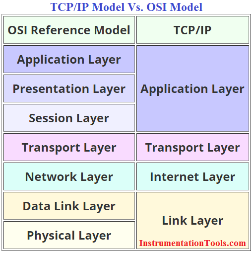
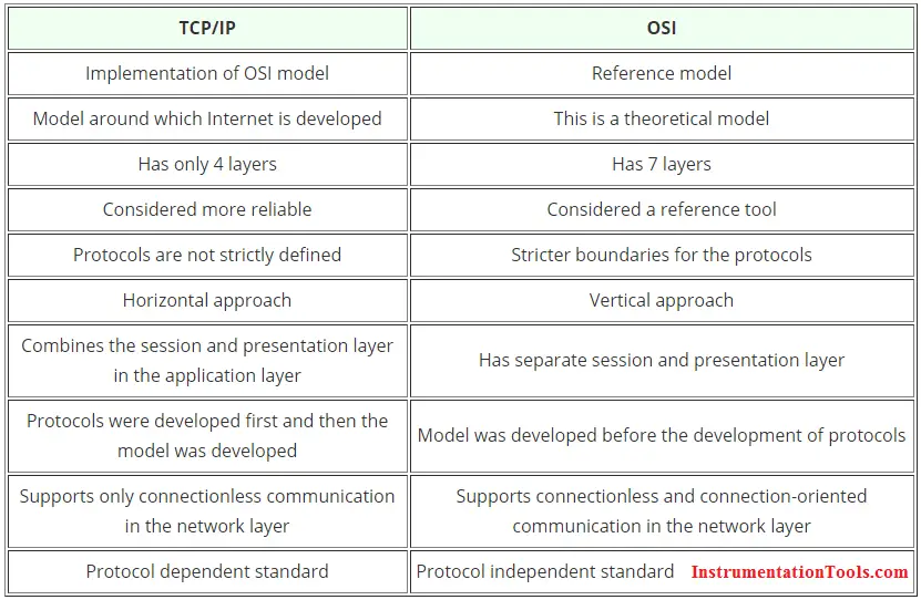
Both the TCP/IP and OSI model work in a very similar fashion. But they do have very subtle differences too. The most apparent difference is the number of layers. TCP/IP is a four-layered structure, while OSI is a seven-layered model.
TCP/IP Model
The Internet Protocol Suite, popularly known as the TCP/IP model, is a communication protocol that is used over the Internet. This model divides the entire networking functions into layers, where each layer performs a specific function.
This model gives a brief idea about the process of data formatting, transmission, and finally the reception. Each of these functions take place in the layers, as described by the model. TCP/IP is a four-layered structure, with each layer having their individual protocol. Let us have a look at the four layers:
Link Layer
As the name suggests, this layer includes the physical and logical connections from the host’s link. It is also known as Network Access layer and Network Interface layer. It explains how the data is transmitted from the host, through the network. The physical connectors like the coaxial cables, twisted pair wires, the optical fiber, interface cards, etc., are a part of this layer. This layer can be used to connect different network types like ATM, Token ring, Ethernet, LAN, etc.
Internet Layer
This layer is also known as the Network Layer. The main function of this layer is to route the data to its destination. The data that is received by the link layer is made into data packets (IP datagrams). The data packets contain the source and the destination IP address or logical address. These packets are sent on any network and are delivered independently. This indicates that the data is not received in the same order as it was sent. The protocols at this layer are IP (Internet Protocol), ICMP (Internet Control Message Protocol), etc.
Transport Layer
This layer is responsible for providing datagram services to the Application layer. This layer allows the host and the destination devices to communicate with each other for exchanging messages, irrespective of the underlying network type. Error control, congestion control, flow control, etc., are handled by the transport layer. The protocol that this layer uses is TCP (Transmission Control Protocol) and UDP (User Datagram Protocol). TCP gives a reliable, end-to-end, connection-oriented data transfer, while UDP provides unreliable, connectionless data transfer between two computers.
Application Layer
It provides the user interface for communication. This is the layer where email, web browsers or FTP run. The protocols in this layer are FTP, SMTP, HTTP, etc.
OSI Model
The Open Systems Interconnected (OSI) model divides the network into seven layers and explains the routing of the data from source to destination. It is a theoretical model which explains the working of the networks. It was developed by the International Organization for Standardization (ISO) for their own network suite. Here are the details of OSI’s seven layers:
Physical Layer
As the name suggests, this is the layer where the physical connection between two computers takes place. The data is transmitted via this physical medium to the destination’s physical layer. The popular protocols at this layer are Fast Ethernet, ATM, RS232, etc.
Data Link Layer
The main function of this layer is to convert the data packets received from the upper layer into frames, and route the same to the physical layer. Error detection and correction is done at this layer, thus making it a reliable layer in the model. It establishes a logical link between the nodes and transmit frames sequentially.
Network Layer
The main function of this layer is to translate the network address into physical MAC address. The data has to be routed to its intended destination on the network. This layer is also responsible to determine the efficient route for transmitting the data to its destination. While doing so, it has to manage problems like network congestion, switching problems, etc. The protocols used here are IP, ICMP, IGMP, IPX, etc.
Transport Layer
This layer provides end-to-end delivery of data between two nodes. It divides data into different packets before transmitting it. On receipt of these packets, the data is reassembled and forwarded to the next layer. If the data is lost in transmission or has errors, then this layer recovers the lost data and transmits the same.
Session Layer
This layer is responsible to establish and terminate connections between two communicating machines. This connection is known as a session, hence the name. It establishes full-duplex, half-duplex and simplex connection for communication. The sessions are also used to keep a track of the connections to the web server.
Presentation Layer
The data conversion takes place at this layer. The data that it receives from the application layer is converted into a suitable format that is recognized by the computer. For example, the conversion of a file from .wav to .mp3 takes place at this layer.
Application Layer
This layer provides a user interface by interacting with the running application. E-mail, FTP, web browsers, etc., are the network applications that run on this layer.
The entire communication industry stands on the backbone of TCP/IP and OSI reference model. It is absolutely vital to learn the above differences, if anyone wants to be an expert in the field of communication.